Getting Started Guide
Page 5
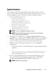
.../DVD, DVD+/-RW, or backup device. Up to view processor information. single or dual rank. • Support for the following internal hard-drive (non-hot-pluggable) configurations: - Getting Started With Your System 3 See the Hardware Owner's Manual. • A minimum of 512 MB of 8 GB DDR II SDRAM memory by region. Up to two internal 3.5-inch Serial-Attached SCSI (SAS) hard drives with an integrated SATA controller or - Dual-Core Intel Xeon® processor - NOTE: DVD devices are data...
.../DVD, DVD+/-RW, or backup device. Up to view processor information. single or dual rank. • Support for the following internal hard-drive (non-hot-pluggable) configurations: - Getting Started With Your System 3 See the Hardware Owner's Manual. • A minimum of 512 MB of 8 GB DDR II SDRAM memory by region. Up to two internal 3.5-inch Serial-Attached SCSI (SAS) hard drives with an integrated SATA controller or - Dual-Core Intel Xeon® processor - NOTE: DVD devices are data...
Getting Started Guide
Page 6
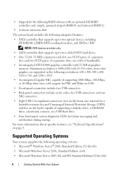
... support for PXE and Wake-on-LAN. • Front-panel connectors include two USB connectors. • Back-panel connectors include serial, video, five USB connectors, and one NIC connector. • Eight USB 2.0-compliant connectors (two on the front, one internal for a bootable memory key and Unmanaged Internal Persistent Storage (UIPS), and five on page 8. true-color graphics are data only. • SATA controller that supports up to two optical devices including DVD-ROM, CDRW/DVD combination drive, and DVD+/- RW. NOTE: DVD devices are supported...
... support for PXE and Wake-on-LAN. • Front-panel connectors include two USB connectors. • Back-panel connectors include serial, video, five USB connectors, and one NIC connector. • Eight USB 2.0-compliant connectors (two on the front, one internal for a bootable memory key and Unmanaged Internal Persistent Storage (UIPS), and five on page 8. true-color graphics are data only. • SATA controller that supports up to two optical devices including DVD-ROM, CDRW/DVD combination drive, and DVD+/- RW. NOTE: DVD devices are supported...
Hardware Owner's Manual
Page 6
... System Battery 88 Installing the System Battery 89 Power Supply 90 Removing the Power Supply 90 Installing the Power Supply 92 Chassis Intrusion Switch 92 Removing the Chassis Intrusion Switch 92 Installing the Chassis Intrusion Switch 93 Bezel (Service Only Parts Procedure 94 Removing the Bezel 94 Replacing the Bezel 95 I/O Panel Assembly (Service Only Parts Procedure 96 Removing the I/O Panel Assembly 96 Replacing the I/O Panel Assembly 97 System Board (Service Only Parts Procedure) . . . . . 99 Removing the System Board 99 Installing the System Board 100 4 Troubleshooting...
... System Battery 88 Installing the System Battery 89 Power Supply 90 Removing the Power Supply 90 Installing the Power Supply 92 Chassis Intrusion Switch 92 Removing the Chassis Intrusion Switch 92 Installing the Chassis Intrusion Switch 93 Bezel (Service Only Parts Procedure 94 Removing the Bezel 94 Replacing the Bezel 95 I/O Panel Assembly (Service Only Parts Procedure 96 Removing the I/O Panel Assembly 96 Replacing the I/O Panel Assembly 97 System Board (Service Only Parts Procedure) . . . . . 99 Removing the System Board 99 Installing the System Board 100 4 Troubleshooting...
Hardware Owner's Manual
Page 23
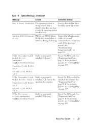
.... Bus#nn/Dev#nn/Funcn Reseat the PCIe cards. Option ROM Checksum Error PCI device BIOS (Option Ensure that does not have a bootable operating system installed on page 139. Actual Link Width is cables are securely detected during shadowing. If the problem persists, see "Getting Help" on page 124. diskette that all appropriate ROM) checksum failure is n PCIe Degraded Link Faulty or improperly Width Error: Slot n installed PCIe card in the specified slot number. See "Expansion Cards...
.... Bus#nn/Dev#nn/Funcn Reseat the PCIe cards. Option ROM Checksum Error PCI device BIOS (Option Ensure that does not have a bootable operating system installed on page 139. Actual Link Width is cables are securely detected during shadowing. If the problem persists, see "Getting Help" on page 124. diskette that all appropriate ROM) checksum failure is n PCIe Degraded Link Faulty or improperly Width Error: Slot n installed PCIe card in the specified slot number. See "Expansion Cards...
Hardware Owner's Manual
Page 24
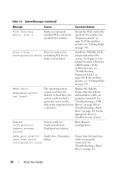
... installed PCIe card in Configuration Error initializing PCI device; Plug & Play Error encountered in the specified slot number. See Figure 6-1 for a BIOS update. If the problem persists, see "Getting Help" on page 121. 24 About Your System "Troubleshooting a Hard Drive" on page 121 for the appropriate drive(s) installed in the specified slot number. Parameters hard disk drive failure. Check for jumper location. faulty system board. Remote Configuration update attempt failed System could not find a properly connected. SATA port A/B/C/D Faulty drive...
... installed PCIe card in Configuration Error initializing PCI device; Plug & Play Error encountered in the specified slot number. See Figure 6-1 for a BIOS update. If the problem persists, see "Getting Help" on page 121. 24 About Your System "Troubleshooting a Hard Drive" on page 121 for the appropriate drive(s) installed in the specified slot number. Parameters hard disk drive failure. Check for jumper location. faulty system board. Remote Configuration update attempt failed System could not find a properly connected. SATA port A/B/C/D Faulty drive...
Hardware Owner's Manual
Page 25
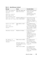
... correct the settings. See "Using the System Setup Program" on page 121. Shutdown failure Shutdown test failure. Faulty memory module. See "Troubleshooting a Hard Drive" on page 29. Ensure that the hard drive cables are properly installed. The amount of system memory has changed the memory configuration. If the problem persists, see "Getting Help" on page 121 for the appropriate drive installed in your system. SATA port A/B/C/D hard disk drive auto-sensing error Ensure that all memory modules are properly connected. Sector...
... correct the settings. See "Using the System Setup Program" on page 121. Shutdown failure Shutdown test failure. Faulty memory module. See "Troubleshooting a Hard Drive" on page 29. Ensure that the hard drive cables are properly installed. The amount of system memory has changed the memory configuration. If the problem persists, see "Getting Help" on page 121 for the appropriate drive installed in your system. SATA port A/B/C/D hard disk drive auto-sensing error Ensure that all memory modules are properly connected. Sector...
Hardware Owner's Manual
Page 35
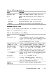
... Diskette Controller Enables the diskette controller. If Console Redirection is Enabled, Serial Port 1 is automatically set to Auto (the default), each channel of the selected hard drive. Using the System Setup Program 35 Table 2-6. Changes take effect after the system reboots. Displays the total capacity of the selected hard drive. Options (All Ports On default) are Enabled with PXE default) Enables or disables the system's integrated NIC. Enables (Auto) or disables (Off) the SATA hard drive in Port X. Integrated Devices Screen Table 2-6 lists the...
... Diskette Controller Enables the diskette controller. If Console Redirection is Enabled, Serial Port 1 is automatically set to Auto (the default), each channel of the selected hard drive. Using the System Setup Program 35 Table 2-6. Changes take effect after the system reboots. Displays the total capacity of the selected hard drive. Options (All Ports On default) are Enabled with PXE default) Enables or disables the system's integrated NIC. Enables (Auto) or disables (Off) the SATA hard drive in Port X. Integrated Devices Screen Table 2-6 lists the...
Hardware Owner's Manual
Page 36
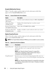
... Screen Options Option System Password Setup Password Description Displays the current status of your system's password security feature and allows you restrict access to Off or Serial Port 1. Console Redirection Screen Table 2-7 lists the options and descriptions for console redirection. Console Redirection Screen Options Option Description Console Redirection (Off default) Sets the console redirection feature to your system (Enabled default) restarts. NOTE: The Trusted Platform Module (TPM) may not be...
... Screen Options Option System Password Setup Password Description Displays the current status of your system's password security feature and allows you restrict access to Off or Serial Port 1. Console Redirection Screen Table 2-7 lists the options and descriptions for console redirection. Console Redirection Screen Options Option Description Console Redirection (Off default) Sets the console redirection feature to your system (Enabled default) restarts. NOTE: The Trusted Platform Module (TPM) may not be...
Hardware Owner's Manual
Page 39
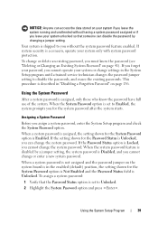
.... Using the System Setup Program 39 If you forget your password, you cannot operate your system only with system password protection. NOTICE: Anyone can access the data stored on the system board is in the enabled (default) position, the setting shown for the System Password option is Not Enabled and the Password Status field is set to Enabled, the system prompts you cannot change the system password. When a system password...
.... Using the System Setup Program 39 If you forget your password, you cannot operate your system only with system password protection. NOTICE: Anyone can access the data stored on the system board is in the enabled (default) position, the setting shown for the System Password option is Not Enabled and the Password Status field is set to Enabled, the system prompts you cannot change the system password. When a system password...
Hardware Owner's Manual
Page 108
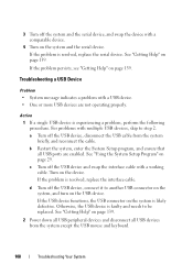
Troubleshooting a USB Device Problem • System message indicates a problem with multiple USB devices, skip to another USB connector on the system, and turn on the system is experiencing a problem, perform the following procedure. See "Using the System Setup Program" on page 139. d Turn off the USB device, connect it to step 2. If the problem is faulty and needs to be replaced. See "Getting Help" on page 29. Otherwise, the USB device is resolved...
Troubleshooting a USB Device Problem • System message indicates a problem with multiple USB devices, skip to another USB connector on the system, and turn on the system is experiencing a problem, perform the following procedure. See "Using the System Setup Program" on page 139. d Turn off the USB device, connect it to step 2. If the problem is faulty and needs to be replaced. See "Getting Help" on page 29. Otherwise, the USB device is resolved...
Hardware Owner's Manual
Page 110
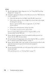
... "Using Dell PowerEdge Diagnostics" on page 129. 2 Check the appropriate indicator on page 139. 110 Troubleshooting Your System See "Using the System Setup Program" on page 29. 5 Ensure that the appropriate drivers are installed and the protocols are enabled. Remove and reinstall the drivers if applicable. If you are using a NIC card instead of an integrated NIC, see "Getting Help" on the NIC connector. See the NIC's documentation. 4 Enter the System Setup...
... "Using Dell PowerEdge Diagnostics" on page 129. 2 Check the appropriate indicator on page 139. 110 Troubleshooting Your System See "Using the System Setup Program" on page 29. 5 Ensure that the appropriate drivers are installed and the protocols are enabled. Remove and reinstall the drivers if applicable. If you are using a NIC card instead of an integrated NIC, see "Getting Help" on the NIC connector. See the NIC's documentation. 4 Enter the System Setup...
Hardware Owner's Manual
Page 114
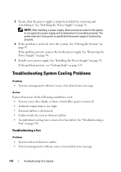
... "Troubleshooting a Fan" on page 92. See "Removing the Power Supply" on page 139. Troubleshooting System Cooling Problems Problem • Systems management software issues a fan-related error message. Troubleshooting a Fan Problem • System-status indicator is removed or has failed. Action Ensure that none of the following conditions exist: • System cover, drive blank, or front or back filler panel is removed. • Ambient temperature is too high. • External airflow is obstructed. • Cables inside...
... "Troubleshooting a Fan" on page 92. See "Removing the Power Supply" on page 139. Troubleshooting System Cooling Problems Problem • Systems management software issues a fan-related error message. Troubleshooting a Fan Problem • System-status indicator is removed or has failed. Action Ensure that none of the following conditions exist: • System cover, drive blank, or front or back filler panel is removed. • Ambient temperature is too high. • External airflow is obstructed. • Cables inside...
Hardware Owner's Manual
Page 117
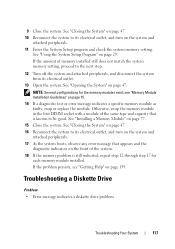
...: Several configurations for each memory module installed. If the problem persists, see "Memory Module Installation Guidelines" on the system and attached peripherals. 11 Enter the System Setup program and check the system memory setting. See "Opening the System" on page 139. Troubleshooting a Diskette Drive Problem • Error message indicates a diskette drive problem. Otherwise, swap the memory module in the first DIMM socket with a module of the same type and capacity that appears and the diagnostic indicators...
...: Several configurations for each memory module installed. If the problem persists, see "Memory Module Installation Guidelines" on the system and attached peripherals. 11 Enter the System Setup program and check the system memory setting. See "Opening the System" on page 139. Troubleshooting a Diskette Drive Problem • Error message indicates a diskette drive problem. Otherwise, swap the memory module in the first DIMM socket with a module of the same type and capacity that appears and the diagnostic indicators...
Hardware Owner's Manual
Page 120
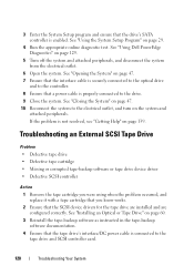
... the interface cable is securely connected to the optical drive and to the controller. 8 Ensure that a power cable is connected to the tape drive and SCSI controller card. 120 Troubleshooting Your System Troubleshooting an External SCSI Tape Drive Problem • Defective tape drive • Defective tape cartridge • Missing or corrupted tape-backup software or tape drive device driver • Defective SCSI controller Action 1 Remove the tape cartridge you were using when the problem occurred, and replace it...
... the interface cable is securely connected to the optical drive and to the controller. 8 Ensure that a power cable is connected to the tape drive and SCSI controller card. 120 Troubleshooting Your System Troubleshooting an External SCSI Tape Drive Problem • Defective tape drive • Defective tape cartridge • Missing or corrupted tape-backup software or tape drive device driver • Defective SCSI controller Action 1 Remove the tape cartridge you were using when the problem occurred, and replace it...
Hardware Owner's Manual
Page 122
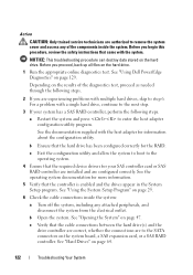
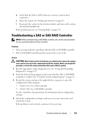
... the controller is enabled and the drives appear in the System Setup program. See "Using the System Setup Program" on the system board, a SAS expansion card, or a SAS RAID controller. For a problem with a single hard drive, continue to the next step. 3 If your SAS controller card or SAS RAID controller are installed and are configured correctly. See the documentation supplied with the system. c Exit the configuration utility and allow the system to boot to the operating system. 4 Ensure that the required device drivers...
... the controller is enabled and the drives appear in the System Setup program. See "Using the System Setup Program" on the system board, a SAS expansion card, or a SAS RAID controller. For a problem with a single hard drive, continue to the next step. 3 If your SAS controller card or SAS RAID controller are installed and are configured correctly. See the documentation supplied with the system. c Exit the configuration utility and allow the system to boot to the operating system. 4 Ensure that the required device drivers...
Hardware Owner's Manual
Page 123
If the problem persists, see the documentation for information about configuration settings. 4 Check the configuration settings, make any of the components inside the system. Problem • Error message indicates a problem with the system. 1 Run the appropriate online diagnostic test. See "Using the System Setup Program" on page 29. 3 Restart the system and press the applicable key sequence to remove the system cover and access any necessary corrections, and restart the system...
If the problem persists, see the documentation for information about configuration settings. 4 Check the configuration settings, make any of the components inside the system. Problem • Error message indicates a problem with the system. 1 Run the appropriate online diagnostic test. See "Using the System Setup Program" on page 29. 3 Restart the system and press the applicable key sequence to remove the system cover and access any necessary corrections, and restart the system...
Hardware Owner's Manual
Page 129
... an error is detected or terminate testing when a user-defined error limit is a suite of menus and options for particular device groups or devices. Dell PowerEdge Diagnostics is reached. • View help you solve the problem. Running the System Diagnostics If you experience a problem with your system, run PowerEdge Diagnostics for systems running supported Microsoft® Windows® and Linux operating systems are available at support.dell.com and on chassis and storage components such as hard drives, physical memory...
... an error is detected or terminate testing when a user-defined error limit is a suite of menus and options for particular device groups or devices. Dell PowerEdge Diagnostics is reached. • View help you solve the problem. Running the System Diagnostics If you experience a problem with your system, run PowerEdge Diagnostics for systems running supported Microsoft® Windows® and Linux operating systems are available at support.dell.com and on chassis and storage components such as hard drives, physical memory...
Hardware Owner's Manual
Page 141
.... A battery that maintains system configuration, date, and time information in the form of a pattern of three beeps is turned off. BIOS - The BIOS controls the following: • Communications between the processor and peripheral devices • Miscellaneous functions, such as system messages bit - The modules are mounted into a chassis that contains a processor, memory, and a hard drive. A - Advanced Configuration and Power Interface. A standard interface for security or tracking purposes. Software designed to direct configuration and power management. Applications run...
.... A battery that maintains system configuration, date, and time information in the form of a pattern of three beeps is turned off. BIOS - The BIOS controls the following: • Communications between the processor and peripheral devices • Miscellaneous functions, such as system messages bit - The modules are mounted into a chassis that contains a processor, memory, and a hard drive. A - Advanced Configuration and Power Interface. A standard interface for security or tracking purposes. Software designed to direct configuration and power management. Applications run...
Hardware Owner's Manual
Page 150
... multiple USB-compliant devices, such as the last device at each end of wiring used to connect systems in the C programming language. A BIOS-based program that automatically supplies power to Linux, is running. UNIX - See RAM. uplink port - Universal Serial Bus. UPS - system diskette - system memory - UNIX, the precursor to your system's hardware and customize the system's operation by changing settings in a series, you start -up file for the Windows operating...
... multiple USB-compliant devices, such as the last device at each end of wiring used to connect systems in the C programming language. A BIOS-based program that automatically supplies power to Linux, is running. UNIX - See RAM. uplink port - Universal Serial Bus. UPS - system diskette - system memory - UNIX, the precursor to your system's hardware and customize the system's operation by changing settings in a series, you start -up file for the Windows operating...
Hardware Owner's Manual
Page 156
... system battery, 88 system board, 99 tape drive, 57 156 Index replacing bezel, 95 chassis intrusion switch, 93 cooling fans, 86 diskette drive, 54 expansion cards, 72 front drive bezel, 49 I/O panel, 97 memory, 77 power supply, 92 processor, 82 system board, 100 S safety, 103 SAS controller card installing, 73 troubleshooting, 123 SAS hard drive. securing your system, 40 serial port connector, 13 setup password assigning, 42 changing, 43 features, 38 working with, 42 startup accessing system features, 10 support contacting Dell, 139 See hard drive. SATA hard drive.
... system battery, 88 system board, 99 tape drive, 57 156 Index replacing bezel, 95 chassis intrusion switch, 93 cooling fans, 86 diskette drive, 54 expansion cards, 72 front drive bezel, 49 I/O panel, 97 memory, 77 power supply, 92 processor, 82 system board, 100 S safety, 103 SAS controller card installing, 73 troubleshooting, 123 SAS hard drive. securing your system, 40 serial port connector, 13 setup password assigning, 42 changing, 43 features, 38 working with, 42 startup accessing system features, 10 support contacting Dell, 139 See hard drive. SATA hard drive.


