Information Update
Page 2
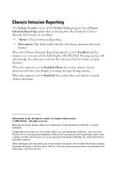
... the written permission of Dell Inc. Dell Inc. in this document to refer to Enabled and the chassis cover is removed, the field displays DETECTED. All rights reserved. When the option is missing from the Hardware Owner's Manual. Microsoft and Windows Server are trademarks of the System Setup program has a Chassis Intrusion Reporting option that...
... the written permission of Dell Inc. Dell Inc. in this document to refer to Enabled and the chassis cover is removed, the field displays DETECTED. All rights reserved. When the option is missing from the Hardware Owner's Manual. Microsoft and Windows Server are trademarks of the System Setup program has a Chassis Intrusion Reporting option that...
Information Update
Page 12
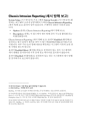
Chassis Intrusion Reporting System Setup System Security Chassis Intrusion Reporting Option (옵션): Chassis Intrusion Reporting Description Chassis Intrusion Reporting Enabled DETECTED Enabled-Silent Disabled 2008 Dell Inc Dell Inc Dell 및 DELL 로고는 Dell Inc Microsoft 및 Windows Server Microsoft Corporation Red Hat 및 Enterprise Linux Red Hat, Inc Dell Inc
Chassis Intrusion Reporting System Setup System Security Chassis Intrusion Reporting Option (옵션): Chassis Intrusion Reporting Description Chassis Intrusion Reporting Enabled DETECTED Enabled-Silent Disabled 2008 Dell Inc Dell Inc Dell 및 DELL 로고는 Dell Inc Microsoft 및 Windows Server Microsoft Corporation Red Hat 및 Enterprise Linux Red Hat, Inc Dell Inc
Getting Started Guide
Page 6
... with x4 bandwidth. • An integrated ATI ES1000 graphics controller with an optional SAS RAID controller card: simple, spanned, striped (RAID 0), and mirrored (RAID 1). • A chassis intrusion alert. true-color graphics are data only. • SATA controller that supports up to two optical devices including DVD-ROM, CDRW/DVD combination drive, and...
... with x4 bandwidth. • An integrated ATI ES1000 graphics controller with an optional SAS RAID controller card: simple, spanned, striped (RAID 0), and mirrored (RAID 1). • A chassis intrusion alert. true-color graphics are data only. • SATA controller that supports up to two optical devices including DVD-ROM, CDRW/DVD combination drive, and...
Hardware Owner's Manual
Page 6
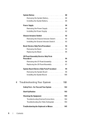
... System Battery 88 Installing the System Battery 89 Power Supply 90 Removing the Power Supply 90 Installing the Power Supply 92 Chassis Intrusion Switch 92 Removing the Chassis Intrusion Switch 92 Installing the Chassis Intrusion Switch 93 Bezel (Service Only Parts Procedure 94 Removing the Bezel 94 Replacing the Bezel 95 I/O Panel Assembly (Service Only Parts...
... System Battery 88 Installing the System Battery 89 Power Supply 90 Removing the Power Supply 90 Installing the Power Supply 92 Chassis Intrusion Switch 92 Removing the Chassis Intrusion Switch 92 Installing the Chassis Intrusion Switch 93 Bezel (Service Only Parts Procedure 94 Removing the Bezel 94 Replacing the Bezel 95 I/O Panel Assembly (Service Only Parts...
Hardware Owner's Manual
Page 45
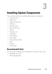
... drives • Hard drives • Expansion cards • SAS controller card • Memory • Microprocessor • Cooling fans • System battery • Power supply • Chassis intrusion switch • Bezel • I/O panel • System board Recommended Tools You may need the following items to perform the procedures in this section: • #2 Phillips...
... drives • Hard drives • Expansion cards • SAS controller card • Memory • Microprocessor • Cooling fans • System battery • Power supply • Chassis intrusion switch • Bezel • I/O panel • System board Recommended Tools You may need the following items to perform the procedures in this section: • #2 Phillips...
Hardware Owner's Manual
Page 47
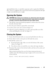
Before you open and close the cover, the chassis intrusion detector, if enabled, causes the following message to remove the system cover and access any of the components inside the system. 3 Reinstall the system cover: a ... for SAS hard drives. See Figure 3-2. See Figure 3-2. b Press down on the cover until the cover release tab snaps into the bottom of the system chassis. Opening the System CAUTION: Only trained service technicians are authorized to appear on the system and attached peripherals. Closing the System 1 Ensure that all internal...
Before you open and close the cover, the chassis intrusion detector, if enabled, causes the following message to remove the system cover and access any of the components inside the system. 3 Reinstall the system cover: a ... for SAS hard drives. See Figure 3-2. See Figure 3-2. b Press down on the cover until the cover release tab snaps into the bottom of the system chassis. Opening the System CAUTION: Only trained service technicians are authorized to appear on the system and attached peripherals. Closing the System 1 Ensure that all internal...

Hardware Owner's Manual
Page 48
5 To reset the chassis intrusion detector, press to enter the System Setup program. Opening and Closing the System 1 1 release tab Front Drive Bezel The front drive bezel is the cover for information on page 29. To remove or install a drive, you must first remove the front drive bezel. 48 Installing System Components See "Using the System Setup Program" on resetting the chassis intrusion detector. NOTE: If a setup password has been assigned by someone else, contact your network administrator for the optional diskette and 5.25-inch drives. Figure 3-2.
5 To reset the chassis intrusion detector, press to enter the System Setup program. Opening and Closing the System 1 1 release tab Front Drive Bezel The front drive bezel is the cover for information on page 29. To remove or install a drive, you must first remove the front drive bezel. 48 Installing System Components See "Using the System Setup Program" on resetting the chassis intrusion detector. NOTE: If a setup password has been assigned by someone else, contact your network administrator for the optional diskette and 5.25-inch drives. Figure 3-2.

Hardware Owner's Manual
Page 92
See "Opening the System" on page 47. 3 Disconnect the chassis intrusion switch cable from the electrical outlet. 2 Open the system. See "Closing the System" on the system board. See Figure 3-28. 92 Installing System Components ...the routing clip on the system board • Hard drives • Diskette drive • Tape backup unit • Optical drives 7 Close the system. Chassis Intrusion Switch Removing the Chassis Intrusion Switch CAUTION: Only trained service technicians are authorized to remove the system cover and access any of the power supply. 6 Depending on your system...
See "Opening the System" on page 47. 3 Disconnect the chassis intrusion switch cable from the electrical outlet. 2 Open the system. See "Closing the System" on the system board. See Figure 3-28. 92 Installing System Components ...the routing clip on the system board • Hard drives • Diskette drive • Tape backup unit • Optical drives 7 Close the system. Chassis Intrusion Switch Removing the Chassis Intrusion Switch CAUTION: Only trained service technicians are authorized to remove the system cover and access any of the power supply. 6 Depending on your system...

Hardware Owner's Manual
Page 93
... the securing bracket notch. 3 Connect the switch cable to the INTRUSION SWITCH connector on the system board. Removing and Installing the Chassis Intrusion Switch 1 2 3 1 chassis intrusion switch 3 INTRUSION SWITCH connector 2 securing bracket notch Installing the Chassis Intrusion Switch 1 Align the chassis intrusion switch with the securing bracket notch. 4 Slide the chassis intrusion switch out of the securing bracket notch. Figure 3-28. Installing...
... the securing bracket notch. 3 Connect the switch cable to the INTRUSION SWITCH connector on the system board. Removing and Installing the Chassis Intrusion Switch 1 2 3 1 chassis intrusion switch 3 INTRUSION SWITCH connector 2 securing bracket notch Installing the Chassis Intrusion Switch 1 Align the chassis intrusion switch with the securing bracket notch. 4 Slide the chassis intrusion switch out of the securing bracket notch. Figure 3-28. Installing...

Hardware Owner's Manual
Page 135
System Board Connectors Item Connector 1 CONTROL_PANEL 2 INTRUSION SWITCH 3 USB3/USB4/USB5 4 NIC1/USB1/USB2 5 PWR_CONN 6 VGA 22 21 20 19 18 Description front panel chassis intrusion switch connector USB connectors NIC and USB connectors power connector video connector Jumpers and Connectors 135 Figure 6-2. System Board Connectors 12 3 4 5 6 7 8 9 10 11 12 13 14 15 28 27 26 25 16 17 24 23 Table 6-2.
System Board Connectors Item Connector 1 CONTROL_PANEL 2 INTRUSION SWITCH 3 USB3/USB4/USB5 4 NIC1/USB1/USB2 5 PWR_CONN 6 VGA 22 21 20 19 18 Description front panel chassis intrusion switch connector USB connectors NIC and USB connectors power connector video connector Jumpers and Connectors 135 Figure 6-2. System Board Connectors 12 3 4 5 6 7 8 9 10 11 12 13 14 15 28 27 26 25 16 17 24 23 Table 6-2.

Hardware Owner's Manual
Page 153
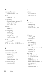
...replacing, 95 bezel (front drive) insert, 50 removing, 49 replacing, 49 C cable clip, 91 CD/DVD drive installing, 60 removing, 57 troubleshooting, 119 chassis intrusion switch installing, 93 removing, 92 replacing, 93 checking equipment, 104 closing the system, 47 connecting external devices, 14 connectors, 134 back-panel, 13 front-panel..., 11 NICs, 13 serial port, 13 USB, 11, 13 video, 13 Console Redirection screen, 36 contacting Dell, 139 cooling fans installing, 86 removing, 83 replacing, 86 troubleshooting, 114 CPU Information screen, 33 Index 153
...replacing, 95 bezel (front drive) insert, 50 removing, 49 replacing, 49 C cable clip, 91 CD/DVD drive installing, 60 removing, 57 troubleshooting, 119 chassis intrusion switch installing, 93 removing, 92 replacing, 93 checking equipment, 104 closing the system, 47 connecting external devices, 14 connectors, 134 back-panel, 13 front-panel..., 11 NICs, 13 serial port, 13 USB, 11, 13 video, 13 Console Redirection screen, 36 contacting Dell, 139 cooling fans installing, 86 removing, 83 replacing, 86 troubleshooting, 114 CPU Information screen, 33 Index 153
Hardware Owner's Manual
Page 154
... installing 3.5-inch drive, 52 5.25-inch drive, 60 bezel, 95 CD/DVD drive, 60 chassis intrusion switch, 93 cooling fans, 86 diskette drive, 54 expansion cards, 72 154 Index See CD/DVD drive. D damaged systems troubleshooting, 111 Dell contacting, 139 diagnostics advanced testing options, 131 testing options, 130 when to use, 130 DIMM...
... installing 3.5-inch drive, 52 5.25-inch drive, 60 bezel, 95 CD/DVD drive, 60 chassis intrusion switch, 93 cooling fans, 86 diskette drive, 54 expansion cards, 72 154 Index See CD/DVD drive. D damaged systems troubleshooting, 111 Dell contacting, 139 diagnostics advanced testing options, 131 testing options, 130 when to use, 130 DIMM...
Hardware Owner's Manual
Page 156
... Dell, 139 POST accessing system features, 10 power supply installing, 92 removing, 90 replacing, 92 troubleshooting, 113 processor installing, 82 removing, 79 replacing, 82 troubleshooting, 126 R recommended tools, 45 removing 3.5-inch drive, 52 5.25-inch drive, 60 bezel, 94 CD/DVD drive, 57 chassis intrusion ... optical drive, 57 power supply, 90 processor, 79 system battery, 88 system board, 99 tape drive, 57 156 Index replacing bezel, 95 chassis intrusion switch, 93 cooling fans, 86 diskette drive, 54 expansion cards, 72 front drive bezel, 49 I/O panel, 97 memory, 77 power supply,...
... Dell, 139 POST accessing system features, 10 power supply installing, 92 removing, 90 replacing, 92 troubleshooting, 113 processor installing, 82 removing, 79 replacing, 82 troubleshooting, 126 R recommended tools, 45 removing 3.5-inch drive, 52 5.25-inch drive, 60 bezel, 94 CD/DVD drive, 57 chassis intrusion ... optical drive, 57 power supply, 90 processor, 79 system battery, 88 system board, 99 tape drive, 57 156 Index replacing bezel, 95 chassis intrusion switch, 93 cooling fans, 86 diskette drive, 54 expansion cards, 72 front drive bezel, 49 I/O panel, 97 memory, 77 power supply,...


