Getting Started Guide
Page 6
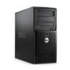
... 32-bit, 33-MHz expansion card slot, one PCI Express x1 expansion slot, and two PCI Express x8 expansion slots; For more information about specific features, see "Technical Specifications" on the back) capable of supporting a diskette drive, a CD-ROM drive, a keyboard, a mouse, or a USB flash drive. • Four front-panel system diagnostic...
... 32-bit, 33-MHz expansion card slot, one PCI Express x1 expansion slot, and two PCI Express x8 expansion slots; For more information about specific features, see "Technical Specifications" on the back) capable of supporting a diskette drive, a CD-ROM drive, a keyboard, a mouse, or a USB flash drive. • Four front-panel system diagnostic...

Getting Started Guide
Page 10
... operating system documentation that ships with your system. PCI and PCIe 0.5 GB/sec PCIe x1, 3.3-V, 12-V (slot 4) 2 GB/sec PCIe x8 with the system. Technical Specifications Processor Processor type Expansion Bus Bus type Expansion slots PCIe PCI Memory Architecture Memory module sockets • Intel® Celeron® processor • Intel Celeron...
... operating system documentation that ships with your system. PCI and PCIe 0.5 GB/sec PCIe x1, 3.3-V, 12-V (slot 4) 2 GB/sec PCIe x8 with the system. Technical Specifications Processor Processor type Expansion Bus Bus type Expansion slots PCIe PCI Memory Architecture Memory module sockets • Intel® Celeron® processor • Intel Celeron...

Getting Started Guide
Page 13
...) Storage -15.2 to 10,600 m (-50 to 35,000 ft) Getting Started With Your System 11 Environmental NOTE: For additional information about environmental measurements for specific system configurations, see dell.com/environmental_datasheets.
...) Storage -15.2 to 10,600 m (-50 to 35,000 ft) Getting Started With Your System 11 Environmental NOTE: For additional information about environmental measurements for specific system configurations, see dell.com/environmental_datasheets.

Hardware Owner's Manual
Page 9
... provided in this document or as a separate document. • The Getting Started Guide provides an overview of system features, setting up your system, and technical specifications. • CDs or DVDs included with your system provide documentation and tools for any problems indicated by any of the following: • Front or back...
... provided in this document or as a separate document. • The Getting Started Guide provides an overview of system features, setting up your system, and technical specifications. • CDs or DVDs included with your system provide documentation and tools for any problems indicated by any of the following: • Front or back...

Hardware Owner's Manual
Page 14
... for the device specifies otherwise). NIC Indicator Codes The NIC on the back panel has an indicator that accompanied the device for specific installation and configuration instructions. • Always attach an external device while your system and the device are normally included with your ...External Devices When connecting external devices to your system, follow these guidelines: • Most devices must be connected to a specific connector and device drivers must be installed before turning on page 29 for information about enabling, disabling, and configuring I/O ports and connectors.
... for the device specifies otherwise). NIC Indicator Codes The NIC on the back panel has an indicator that accompanied the device for specific installation and configuration instructions. • Always attach an external device while your system and the device are normally included with your ...External Devices When connecting external devices to your system, follow these guidelines: • Most devices must be connected to a specific connector and device drivers must be installed before turning on page 29 for information about enabling, disabling, and configuring I/O ports and connectors.

Hardware Owner's Manual
Page 15
... time that the switch is : The voltage selection switch should be set to: 110 V 115 220 V 230 For information on system power requirements, see "Technical Specifications" in your power source is set to the proper voltage according to the network or the NIC is disabled in the System Setup program. Voltage...
... time that the switch is : The voltage selection switch should be set to: 110 V 115 220 V 230 For information on system power requirements, see "Technical Specifications" in your power source is set to the proper voltage according to the network or the NIC is disabled in the System Setup program. Voltage...

Hardware Owner's Manual
Page 20
... Installation Guidelines" on page 139. 20 About Your System If the problem persists, replace the keyboard. General failure The operating system is usually followed by specific information. page 139. Ensure that mouse and keyboard are not matched pairs. If the problem persists, replace the keyboard. Ensure memory in slots DIMM1_A and...
... Installation Guidelines" on page 139. 20 About Your System If the problem persists, replace the keyboard. General failure The operating system is usually followed by specific information. page 139. Ensure that mouse and keyboard are not matched pairs. If the problem persists, replace the keyboard. Ensure memory in slots DIMM1_A and...

Hardware Owner's Manual
Page 107
If the problem is enabled and configured correctly for specific port configuration requirements that were reset. Action 1 Turn off the system and any custom BIOS settings that the program may require. 3 Run the appropriate online ...
If the problem is enabled and configured correctly for specific port configuration requirements that were reset. Action 1 Turn off the system and any custom BIOS settings that the program may require. 3 Run the appropriate online ...
Hardware Owner's Manual
Page 116
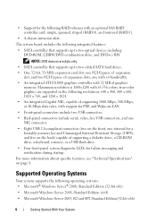
.... See "Memory Module Installation Guidelines" on page 47. 7 Ensure that came with a specific memory module, go to step 12. 5 Turn off the system and attached peripherals, unplug the system from the electrical outlet. 6 Open the system. See "Using Dell PowerEdge Diagnostics" on the screen. Action CAUTION: Only trained service technicians are authorized to...
.... See "Memory Module Installation Guidelines" on page 47. 7 Ensure that came with a specific memory module, go to step 12. 5 Turn off the system and attached peripherals, unplug the system from the electrical outlet. 6 Open the system. See "Using Dell PowerEdge Diagnostics" on the screen. Action CAUTION: Only trained service technicians are authorized to...
Hardware Owner's Manual
Page 117
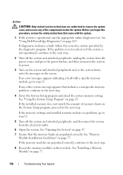
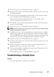
... 47. 10 Reconnect the system to be good. See "Using the System Setup Program" on page 75. 14 If a diagnostic test or error message indicates a specific memory module as faulty, swap or replace the module. see "Getting Help" on the system and attached peripherals. 17 As the system boots, observe any...
... 47. 10 Reconnect the system to be good. See "Using the System Setup Program" on page 75. 14 If a diagnostic test or error message indicates a specific memory module as faulty, swap or replace the module. see "Getting Help" on the system and attached peripherals. 17 As the system boots, observe any...

Hardware Owner's Manual
Page 130
... explanation of that the diagnostics are functioning, you to test only your screen. Using this section, start the system diagnostics, a message is run all or specific diagnostics tests or to exit the system diagnostics. NOTICE: Use the system diagnostics to run from the utility partition on your system.
... explanation of that the diagnostics are functioning, you to test only your screen. Using this section, start the system diagnostics, a message is run all or specific diagnostics tests or to exit the system diagnostics. NOTICE: Use the system diagnostics to run from the utility partition on your system.

Hardware Owner's Manual
Page 131
... you want to select how you select. Selecting Devices for Testing The left side of the Customize window lists devices that can be tested, select specific options for testing. When checked, time stamps the test log. Use this option. • Show Ending Timestamp - Click (+) on any component to view the tests...
... you want to select how you select. Selecting Devices for Testing The left side of the Customize window lists devices that can be tested, select specific options for testing. When checked, time stamps the test log. Use this option. • Show Ending Timestamp - Click (+) on any component to view the tests...

Hardware Owner's Manual
Page 133
Figure 6-1 shows the location of the components inside the system. Jumpers and Connectors This section provides specific information about the system jumpers and describes the connectors on the system board. Before you begin this procedure, review the safety instructions that came with the system. Figure 6-1. System Board Jumpers Jumpers and Connectors 133 Table 6-1 lists the jumper settings. System Board Jumpers CAUTION: Only trained service technicians are authorized to remove the system cover and access any of the configuration jumpers on the various boards in the system.
Figure 6-1 shows the location of the components inside the system. Jumpers and Connectors This section provides specific information about the system jumpers and describes the connectors on the system board. Before you begin this procedure, review the safety instructions that came with the system. Figure 6-1. System Board Jumpers Jumpers and Connectors 133 Table 6-1 lists the jumper settings. System Board Jumpers CAUTION: Only trained service technicians are authorized to remove the system cover and access any of the configuration jumpers on the various boards in the system.
Hardware Owner's Manual
Page 141
... start-up your system documents. BIOS - ASCII - backup battery - Baseboard management controller. Applications run from your operating system. Before making a change to help you perform a specific task or series of three beeps is located. Advanced Configuration and Power Interface. A diagnostic message in a special section of a program or data file. Ampere(s). application...
... start-up your system documents. BIOS - ASCII - backup battery - Baseboard management controller. Applications run from your operating system. Before making a change to help you perform a specific task or series of three beeps is located. Advanced Configuration and Power Interface. A diagnostic message in a special section of a program or data file. Ampere(s). application...

Hardware Owner's Manual
Page 142
... indicator. C - CD - Compact disc. cm - Centimeter(s). Complementary metal-oxide semiconductor. component - Each component is in conventional memory. COM - conventional memory - The first 640 KB of specific processing tasks. A math coprocessor, for communications between the processor and a peripheral. CPU -
... indicator. C - CD - Compact disc. cm - Centimeter(s). Complementary metal-oxide semiconductor. component - Each component is in conventional memory. COM - conventional memory - The first 640 KB of specific processing tasks. A math coprocessor, for communications between the processor and a peripheral. CPU -
Hardware Owner's Manual
Page 146
... confined to the same building or a few nearby buildings, with all equipment linked by wiring dedicated specifically to run much faster than they would with technical support and training are used. Megabits per second. MBR - A specific location, usually expressed as Red Hat® Software. KVM - A LAN is freely available; Liquid crystal display...
... confined to the same building or a few nearby buildings, with all equipment linked by wiring dedicated specifically to run much faster than they would with technical support and training are used. Megabits per second. MBR - A specific location, usually expressed as Red Hat® Software. KVM - A LAN is freely available; Liquid crystal display...
Hardware Owner's Manual
Page 147
... have their own operating systems, integrated hardware, and software that are optimized to signal the processor about hardware errors. A device sends an NMI to serve specific storage needs. The NT File System option in your system. You can contain several different forms of the concepts used for maintaining the date, time...
... have their own operating systems, integrated hardware, and software that are optimized to signal the processor about hardware errors. A device sends an NMI to serve specific storage needs. The NT File System option in your system. You can contain several different forms of the concepts used for maintaining the date, time...
Hardware Owner's Manual
Page 151
... integration through the use of colors. Zero insertion force. video memory - Most VGA and SVGA video adapters include memory chips in addition to display at a specific graphics resolution, you start -up and down. To display a program at a chosen resolution with the desired number of XML Web services. Watt(s). Windows 2000 - XML...
... integration through the use of colors. Zero insertion force. video memory - Most VGA and SVGA video adapters include memory chips in addition to display at a specific graphics resolution, you start -up and down. To display a program at a chosen resolution with the desired number of XML Web services. Watt(s). Windows 2000 - XML...
