
Getting Started Guide
Page 9
Connect the System to Power Connect the system's power cable to the system. Next, plug the other end of the power cable into a grounded electrical outlet or a separate power source such as an uninterrupted power supply (UPS) or a power distribution unit (PDU). Adjust the monitor's controls until the displayed image is satisfactory. The power indicators should light. Turn on the System and Monitor Press the power button on the system and the monitor. Getting Started With Your System 7
Connect the System to Power Connect the system's power cable to the system. Next, plug the other end of the power cable into a grounded electrical outlet or a separate power source such as an uninterrupted power supply (UPS) or a power distribution unit (PDU). Adjust the monitor's controls until the displayed image is satisfactory. The power indicators should light. Turn on the System and Monitor Press the power button on the system and the monitor. Getting Started With Your System 7

Getting Started Guide
Page 12
Connectors (continued) Front USB Internally accessible SATA channels USB key (for memory key) Video Video type Video memory Power AC power supply (per power supply) Wattage Voltage Heat dissipation CMOS Backup Battery Physical Height Width Depth Weight (maximum configuration) one 4-pin USB 2.0-compliant (CD/DVD/USB key) one 4-pin ...
Connectors (continued) Front USB Internally accessible SATA channels USB key (for memory key) Video Video type Video memory Power AC power supply (per power supply) Wattage Voltage Heat dissipation CMOS Backup Battery Physical Height Width Depth Weight (maximum configuration) one 4-pin USB 2.0-compliant (CD/DVD/USB key) one 4-pin ...
Hardware Owner's Manual
Page 3
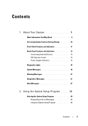
Contents 1 About Your System 9 Other Information You May Need 9 Accessing System Features During Startup 10 Front-Panel Features and Indicators 11 Back-Panel Features and Indicators 13 Connecting External Devices 14 NIC Indicator Codes 14 Power Supply Indicators 15 Diagnostic Lights 16 System Messages 18 Warning Messages 27 Diagnostics Messages 27 Alert Messages 27 2 Using the System Setup Program 29 Entering the System Setup Program 29 Responding to Error Messages 29 Using the System Setup Program 30 Contents 3
Contents 1 About Your System 9 Other Information You May Need 9 Accessing System Features During Startup 10 Front-Panel Features and Indicators 11 Back-Panel Features and Indicators 13 Connecting External Devices 14 NIC Indicator Codes 14 Power Supply Indicators 15 Diagnostic Lights 16 System Messages 18 Warning Messages 27 Diagnostics Messages 27 Alert Messages 27 2 Using the System Setup Program 29 Entering the System Setup Program 29 Responding to Error Messages 29 Using the System Setup Program 30 Contents 3
Hardware Owner's Manual
Page 6
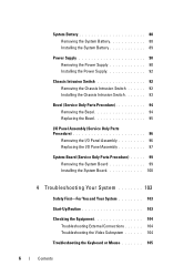
System Battery 88 Removing the System Battery 88 Installing the System Battery 89 Power Supply 90 Removing the Power Supply 90 Installing the Power Supply 92 Chassis Intrusion Switch 92 Removing the Chassis Intrusion Switch 92 Installing the Chassis Intrusion Switch 93 Bezel (Service Only Parts Procedure 94 Removing ...
System Battery 88 Removing the System Battery 88 Installing the System Battery 89 Power Supply 90 Removing the Power Supply 90 Installing the Power Supply 92 Chassis Intrusion Switch 92 Removing the Chassis Intrusion Switch 92 Installing the Chassis Intrusion Switch 93 Bezel (Service Only Parts Procedure 94 Removing ...
Hardware Owner's Manual
Page 7
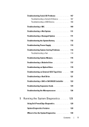
... Device 108 Troubleshooting a NIC 109 Troubleshooting a Wet System 111 Troubleshooting a Damaged System 111 Troubleshooting the System Battery 112 Troubleshooting Power Supply 113 Troubleshooting System Cooling Problems 114 Troubleshooting a Fan 114 Troubleshooting System Memory 115 Troubleshooting a Diskette Drive 117 Troubleshooting an... . . 123 Troubleshooting Expansion Cards 124 Troubleshooting the Microprocessor 126 5 Running the System Diagnostics 129 Using Dell PowerEdge Diagnostics 129 System Diagnostics Features 129 When to Use the System Diagnostics 130 Contents 7
... Device 108 Troubleshooting a NIC 109 Troubleshooting a Wet System 111 Troubleshooting a Damaged System 111 Troubleshooting the System Battery 112 Troubleshooting Power Supply 113 Troubleshooting System Cooling Problems 114 Troubleshooting a Fan 114 Troubleshooting System Memory 115 Troubleshooting a Diskette Drive 117 Troubleshooting an... . . 123 Troubleshooting Expansion Cards 124 Troubleshooting the Microprocessor 126 5 Running the System Diagnostics 129 Using Dell PowerEdge Diagnostics 129 System Diagnostics Features 129 When to Use the System Diagnostics 130 Contents 7

Hardware Owner's Manual
Page 12
... drive. 12 About Your System Steady green - Blinking green - Steady amber - Blinking amber - The system is a problem with the power supply. Holds an optional optical or tape backup unit drive. No light - The system is pressed. If the system is not running an... ACPI-compliant operating system, the system performs a graceful shutdown before Power-On Self Test (POST). There is powered on page 16. Front-Panel Components (continued) Item Component Icon 2 power button 3 power light 4 flex bay 5 lower 5.25-inch drive bay 6 upper 5.25-inch ...
... drive. 12 About Your System Steady green - Blinking green - Steady amber - Blinking amber - The system is a problem with the power supply. Holds an optional optical or tape backup unit drive. No light - The system is pressed. If the system is not running an... ACPI-compliant operating system, the system performs a graceful shutdown before Power-On Self Test (POST). There is powered on page 16. Front-Panel Components (continued) Item Component Icon 2 power button 3 power light 4 flex bay 5 lower 5.25-inch drive bay 6 upper 5.25-inch ...

Hardware Owner's Manual
Page 13
Back-Panel Features and Indicators Figure 1-2 shows the controls, indicators, and connectors located on the system's back panel. Figure 1-2. Back-Panel Features and Indicators 1 2 1 voltage selection switch 3 USB connectors (5) 5 video connector 7 I/O expansion-card slots (4) 3 4 5 6 7 2 power connector 4 NIC connector 6 serial connector About Your System 13
Back-Panel Features and Indicators Figure 1-2 shows the controls, indicators, and connectors located on the system's back panel. Figure 1-2. Back-Panel Features and Indicators 1 2 1 voltage selection switch 3 USB connectors (5) 5 video connector 7 I/O expansion-card slots (4) 3 4 5 6 7 2 power connector 4 NIC connector 6 serial connector About Your System 13

Hardware Owner's Manual
Page 15
... is being sent or received. When off , the NIC is not connected to : 110 V 115 220 V 230 For information on system power requirements, see "Technical Specifications" in your Getting Started Guide. NIC Indicator Codes Indicator Type Indicator Code Activity Off Blinking Link Off Yellow Orange Green...allows you to Table 1-4. See "Using the System Setup Program" on page 29. 1000-Mbps connection 100-Mbps connection 10-Mbps connection Power Supply Indicators The voltage selection switch on page 29. Ensure that the link indicator is off at the same time that network data ...
... is being sent or received. When off , the NIC is not connected to : 110 V 115 220 V 230 For information on system power requirements, see "Technical Specifications" in your Getting Started Guide. NIC Indicator Codes Indicator Type Indicator Code Activity Off Blinking Link Off Yellow Orange Green...allows you to Table 1-4. See "Using the System Setup Program" on page 29. 1000-Mbps connection 100-Mbps connection 10-Mbps connection Power Supply Indicators The voltage selection switch on page 29. Ensure that the link indicator is off at the same time that network data ...
Hardware Owner's Manual
Page 16
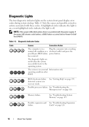
... 124. 16 About Your System Possible expansion card See "Troubleshooting Expansion failure. Cards" on page 126. NOTE: If the power LEDs blink amber, there is on the system front panel display error codes during system startup. Diagnostic Indicator Codes Code Causes Corrective... See "Troubleshooting System Memory" on page 139. The system is off condition or a electrical outlet and press the possible pre-BIOS failure power button. See "Getting Help" on page 115. a non-highlighted circle indicates the light is in a normal Information only. BIOS checksum...
... 124. 16 About Your System Possible expansion card See "Troubleshooting Expansion failure. Cards" on page 126. NOTE: If the power LEDs blink amber, there is on the system front panel display error codes during system startup. Diagnostic Indicator Codes Code Causes Corrective... See "Troubleshooting System Memory" on page 139. The system is off condition or a electrical outlet and press the possible pre-BIOS failure power button. See "Getting Help" on page 115. a non-highlighted circle indicates the light is in a normal Information only. BIOS checksum...
Hardware Owner's Manual
Page 27
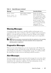
For more information, see the documentation that section for drive, temperature, fan, and power conditions. Alert Messages Systems management software generates alert messages for the appropriate drive(s) installed in that accompanied the operating system or application. NOTE: Warning messages ...
For more information, see the documentation that section for drive, temperature, fan, and power conditions. Alert Messages Systems management software generates alert messages for the appropriate drive(s) installed in that accompanied the operating system or application. NOTE: Warning messages ...

Hardware Owner's Manual
Page 34
...Disabled default) Technology. Enabled permits virtualization software to the operating system. If the processor does not support Demand-Based Power Management, this option for the processor. SATA Configuration Screen Table 2-5 lists the options and descriptions for the information ...Screen (continued) Option Description Logical Processor (Enabled default) Displays when the processor supports Hyper-Threading technology. Demand-Based Power Management (Enabled default) When set to Disabled, the Performance State Tables are reported to be used by the operating...
...Disabled default) Technology. Enabled permits virtualization software to the operating system. If the processor does not support Demand-Based Power Management, this option for the processor. SATA Configuration Screen Table 2-5 lists the options and descriptions for the information ...Screen (continued) Option Description Logical Processor (Enabled default) Displays when the processor supports Hyper-Threading technology. Demand-Based Power Management (Enabled default) When set to Disabled, the Performance State Tables are reported to be used by the operating...

Hardware Owner's Manual
Page 38
...are preserved). On turns on your data requires more security, use additional forms of all user settings for the data on the system after power is set to the operating system and will cause loss of protection, such as data encryption programs. 38 Using the System Setup Program ...displays the following options: • Save Changes and Exit • Discard Changes and Exit • Return to Off, the system remains off after power is restored to enabling this option. The operational state of security for the TPM are cleared. TPM Clear (No default) NOTICE: Clearing the TPM ...
...are preserved). On turns on your data requires more security, use additional forms of all user settings for the data on the system after power is set to the operating system and will cause loss of protection, such as data encryption programs. 38 Using the System Setup Program ...displays the following options: • Save Changes and Exit • Discard Changes and Exit • Return to Off, the system remains off after power is restored to enabling this option. The operational state of security for the TPM are cleared. TPM Clear (No default) NOTICE: Clearing the TPM ...
Hardware Owner's Manual
Page 45
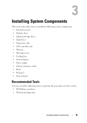
...; Optical and tape drives • Hard drives • Expansion cards • SAS controller card • Memory • Microprocessor • Cooling fans • System battery • Power supply • Chassis intrusion switch • Bezel • I/O panel • System board Recommended Tools You may need the following items to perform the procedures in...
...; Optical and tape drives • Hard drives • Expansion cards • SAS controller card • Memory • Microprocessor • Cooling fans • System battery • Power supply • Chassis intrusion switch • Bezel • I/O panel • System board Recommended Tools You may need the following items to perform the procedures in...
Hardware Owner's Manual
Page 46
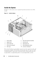
Inside the System 10 1 9 8 2 3 7 6 5 1 power supply 3 system board 5 3.5-inch drive bay 7 5.25-inch drive bays (2) 9 drive cage 4 2 heat sink and shroud assembly 4 hard drives (2) 6 tape backup unit 8 bezel sliding plate ...
Inside the System 10 1 9 8 2 3 7 6 5 1 power supply 3 system board 5 3.5-inch drive bay 7 5.25-inch drive bays (2) 9 drive cage 4 2 heat sink and shroud assembly 4 hard drives (2) 6 tape backup unit 8 bezel sliding plate ...
Hardware Owner's Manual
Page 47
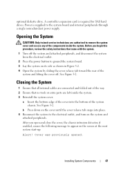
... on the screen at the next system start-up: Alert! b Press down on the system and attached peripherals. Installing System Components 47 Power is required for SAS hard drives. See Figure 3-2. Closing the System 1 Ensure that all internal cables are authorized to remove the system cover... Insert the bottom edge of the cover into place. 4 Reconnect the system to the system board and internal peripherals through a single nonredundant power supply. A controller expansion card is supplied to the electrical outlet, and turn on the cover until the cover release tab snaps into the...
... on the screen at the next system start-up: Alert! b Press down on the system and attached peripherals. Installing System Components 47 Power is required for SAS hard drives. See Figure 3-2. Closing the System 1 Ensure that all internal cables are authorized to remove the system cover... Insert the bottom edge of the cover into place. 4 Reconnect the system to the system board and internal peripherals through a single nonredundant power supply. A controller expansion card is supplied to the electrical outlet, and turn on the cover until the cover release tab snaps into the...

Hardware Owner's Manual
Page 52
See "Opening the System" on page 49. 4 Disconnect the power and data cables from the electrical outlet. 2 Open the system. See "Removing the Front Drive Bezel" on page 47. 3 Remove the front drive bezel. See ...
See "Opening the System" on page 49. 4 Disconnect the power and data cables from the electrical outlet. 2 Open the system. See "Removing the Front Drive Bezel" on page 47. 3 Remove the front drive bezel. See ...

Hardware Owner's Manual
Page 55
See Figure 3-8 and Figure 6-2. Installing System Components 55 Installing Diskette Drive Shoulder Screws 1 1 screws (4) 9 From the front of the chassis, slide the drive into the drive bay until the shoulder screws fit into their slots and snap securely into the sliding plate. 10 Connect the power cable to the diskette drive connector (FLOPPY) on the system board. See Figure 3-6. 11 Connect the data cable from the drive to the drive. Figure 3-7.
See Figure 3-8 and Figure 6-2. Installing System Components 55 Installing Diskette Drive Shoulder Screws 1 1 screws (4) 9 From the front of the chassis, slide the drive into the drive bay until the shoulder screws fit into their slots and snap securely into the sliding plate. 10 Connect the power cable to the diskette drive connector (FLOPPY) on the system board. See Figure 3-6. 11 Connect the data cable from the drive to the drive. Figure 3-7.
Hardware Owner's Manual
Page 56
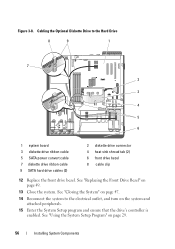
... Installing System Components See "Closing the System" on page 47. 14 Reconnect the system to the Hard Drive 8 9 1 7 2 3 4 5 6 1 system board 3 diskette drive ribbon cable 5 SATA power convert cable 7 diskette drive ribbon cable 9 SATA hard drive cables (2) 2 diskette drive connector 4 heat sink shroud tab (2) 6 front drive bezel 8 cable clip 12 Replace the...
... Installing System Components See "Closing the System" on page 47. 14 Reconnect the system to the Hard Drive 8 9 1 7 2 3 4 5 6 1 system board 3 diskette drive ribbon cable 5 SATA power convert cable 7 diskette drive ribbon cable 9 SATA hard drive cables (2) 2 diskette drive connector 4 heat sink shroud tab (2) 6 front drive bezel 8 cable clip 12 Replace the...

Hardware Owner's Manual
Page 57
... components inside the system. See Figure 3-9 for disconnecting SCSI connections and Figure 3-10 for disconnecting SATA connections. 5 Slide the lever on page 49. 4 Disconnect the power and data cables from the electrical outlet. 2 Open the system. Optical and Tape Drives In the upper 5.25-inch drive bay, you can install only...
... components inside the system. See Figure 3-9 for disconnecting SCSI connections and Figure 3-10 for disconnecting SATA connections. 5 Slide the lever on page 49. 4 Disconnect the power and data cables from the electrical outlet. 2 Open the system. Optical and Tape Drives In the upper 5.25-inch drive bay, you can install only...

Hardware Owner's Manual
Page 61
... Shoulder Screws 1 1 screws (3) 8 Gently slide the drive into place until you hear a click or feel the drive securely installed. 9 Attach the SCSI power cable (see Figure 3-12) or SATA power cable (see Figure 3-13) to the bottom row of holes and two to the drive. 6 If the drive bay is empty, remove...
... Shoulder Screws 1 1 screws (3) 8 Gently slide the drive into place until you hear a click or feel the drive securely installed. 9 Attach the SCSI power cable (see Figure 3-12) or SATA power cable (see Figure 3-13) to the bottom row of holes and two to the drive. 6 If the drive bay is empty, remove...


