Hardware Owner's Manual
Page 5
...; Windows® Operating System Only 76 Removing a Memory Module 77 Installing a Memory Module 77 Microprocessor 79 Removing the Processor 79 Replacing the Processor 82 Cooling Fans 83 Removing the Cooling Fans 83 Replacing the Cooling...
...; Windows® Operating System Only 76 Removing a Memory Module 77 Installing a Memory Module 77 Microprocessor 79 Removing the Processor 79 Replacing the Processor 82 Cooling Fans 83 Removing the Cooling Fans 83 Replacing the Cooling...
Hardware Owner's Manual
Page 7
... 114 Troubleshooting a Fan 114 Troubleshooting System Memory 115 Troubleshooting a Diskette Drive 117 Troubleshooting an Optical Drive 119 Troubleshooting an External SCSI Tape Drive . . . . . 120 Troubleshooting a Hard Drive 121 Troubleshooting a SAS or SAS RAID Controller . . . . 123 Troubleshooting Expansion Cards 124 Troubleshooting the Microprocessor 126 5 Running the System Diagnostics 129 Using Dell PowerEdge Diagnostics 129...
... 114 Troubleshooting a Fan 114 Troubleshooting System Memory 115 Troubleshooting a Diskette Drive 117 Troubleshooting an Optical Drive 119 Troubleshooting an External SCSI Tape Drive . . . . . 120 Troubleshooting a Hard Drive 121 Troubleshooting a SAS or SAS RAID Controller . . . . 123 Troubleshooting Expansion Cards 124 Troubleshooting the Microprocessor 126 5 Running the System Diagnostics 129 Using Dell PowerEdge Diagnostics 129...
Hardware Owner's Manual
Page 27
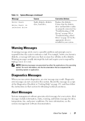
... the message on a copy of the Diagnostics Checklist in "Getting Help" on the diskette. About Your System 27 Table 1-6. Ensure that section for drive, temperature, fan, and power conditions. For more information, see the documentation that you to respond before you format a diskette, a message will warn you that accompanied the operating...
... the message on a copy of the Diagnostics Checklist in "Getting Help" on the diskette. About Your System 27 Table 1-6. Ensure that section for drive, temperature, fan, and power conditions. For more information, see the documentation that you to respond before you format a diskette, a message will warn you that accompanied the operating...
Hardware Owner's Manual
Page 45
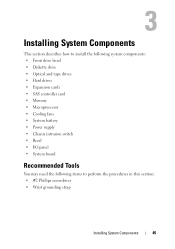
... bezel • Diskette drive • Optical and tape drives • Hard drives • Expansion cards • SAS controller card • Memory • Microprocessor • Cooling fans • System battery • Power supply • Chassis intrusion switch • Bezel • I/O panel • System board Recommended Tools You may need the following items...
... bezel • Diskette drive • Optical and tape drives • Hard drives • Expansion cards • SAS controller card • Memory • Microprocessor • Cooling fans • System battery • Power supply • Chassis intrusion switch • Bezel • I/O panel • System board Recommended Tools You may need the following items...
Hardware Owner's Manual
Page 46
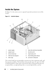
... drive bay 7 5.25-inch drive bays (2) 9 drive cage 4 2 heat sink and shroud assembly 4 hard drives (2) 6 tape backup unit 8 bezel sliding plate release 10 processor cooling fan The system board can accommodate one processor, four expansion cards, and four memory modules. Drive bays in the front of the system.
... drive bay 7 5.25-inch drive bays (2) 9 drive cage 4 2 heat sink and shroud assembly 4 hard drives (2) 6 tape backup unit 8 bezel sliding plate release 10 processor cooling fan The system board can accommodate one processor, four expansion cards, and four memory modules. Drive bays in the front of the system.

Hardware Owner's Manual
Page 63
... are installing a SCSI tape drive, connect the SCSI interface cable in the drive kit from the SCSI controller card to allow for airflow between the fan and cooling vents. 12 Replace the front drive bezel. See Figure 3-12. 11 Check all cable connections, and fold cables out of the way to...
... are installing a SCSI tape drive, connect the SCSI interface cable in the drive kit from the SCSI controller card to allow for airflow between the fan and cooling vents. 12 Replace the front drive bezel. See Figure 3-12. 11 Check all cable connections, and fold cables out of the way to...

Hardware Owner's Manual
Page 74
Figure 3-19. Cabling a SAS or SATA Hard Drive to a SAS Controller Expansion Card 1 2 3 4 5 6 10 9 8 7 1 SAS card 3 power cable 5 power cable 7 front drive bezel 9 retaining tabs on top of heat sink shroud 2 clip on hard disk drive fan shroud 4 hard disk drive fan 6 top notch on heat sink fan shroud 8 SAS cable 10 retaining clip on top of heat sink fan shroud See "Hard Drives" on page 64 for information about connecting hard drives. 74 Installing System Components
Figure 3-19. Cabling a SAS or SATA Hard Drive to a SAS Controller Expansion Card 1 2 3 4 5 6 10 9 8 7 1 SAS card 3 power cable 5 power cable 7 front drive bezel 9 retaining tabs on top of heat sink shroud 2 clip on hard disk drive fan shroud 4 hard disk drive fan 6 top notch on heat sink fan shroud 8 SAS cable 10 retaining clip on top of heat sink fan shroud See "Hard Drives" on page 64 for information about connecting hard drives. 74 Installing System Components

Hardware Owner's Manual
Page 80
These captive screws are adjacent to cool before you touch them. 1 Turn off the system and attached peripherals, and disconnect the system from the fan housing on its pivot bracket and lift it aside. 4 Using a #2 Phillips screwdriver, loosen the two captive screws holding the heat sink and shroud assembly in ... outlet. 2 Open the system. Ensure that is braced on page 47. 3 Detach the diskette cable that they have had sufficient time to the processor cooling fan housing.
These captive screws are adjacent to cool before you touch them. 1 Turn off the system and attached peripherals, and disconnect the system from the fan housing on its pivot bracket and lift it aside. 4 Using a #2 Phillips screwdriver, loosen the two captive screws holding the heat sink and shroud assembly in ... outlet. 2 Open the system. Ensure that is braced on page 47. 3 Detach the diskette cable that they have had sufficient time to the processor cooling fan housing.

Hardware Owner's Manual
Page 83
...the system. 1 Turn off the system and attached peripherals, and disconnect the system from the bottom of the heat sink. Cooling Fans The system contains two cooling fans, one for the processor and one for the card cage. Before you apply new thermal grease. d When the processor is ...them to secure the heat sink assembly to the electrical outlet, and turn on the system and attached peripherals. The fan and shroud are removing the larger processor cooling fan, you are replaced as optimal processor operation. 5 Apply new thermal grease to remove the system cover and access ...
...the system. 1 Turn off the system and attached peripherals, and disconnect the system from the bottom of the heat sink. Cooling Fans The system contains two cooling fans, one for the processor and one for the card cage. Before you apply new thermal grease. d When the processor is ...them to secure the heat sink assembly to the electrical outlet, and turn on the system and attached peripherals. The fan and shroud are removing the larger processor cooling fan, you are replaced as optimal processor operation. 5 Apply new thermal grease to remove the system cover and access ...

Hardware Owner's Manual
Page 84
... chassis (see Figure 3-24). a If you are removing the smaller hard drive cooling fan (see Figure 3-23): b Squeeze the two release tabs together at the top of the fan cage that attaches the processor cooling fan to guide the bottom mounting tabs out of their mounting holes (see Figure 3-24).... d Slide the fan toward the back panel and lift the fan out. 84 Installing System Components Do not remove the processor, however. c Lift the fan out. 3 Disconnect the fan's power cable from the system board. NOTE: The SAS hard drive cooling...
... chassis (see Figure 3-24). a If you are removing the smaller hard drive cooling fan (see Figure 3-23): b Squeeze the two release tabs together at the top of the fan cage that attaches the processor cooling fan to guide the bottom mounting tabs out of their mounting holes (see Figure 3-24).... d Slide the fan toward the back panel and lift the fan out. 84 Installing System Components Do not remove the processor, however. c Lift the fan out. 3 Disconnect the fan's power cable from the system board. NOTE: The SAS hard drive cooling...

Hardware Owner's Manual
Page 85
Removing and Installing the SAS Controller Cooling Fan 1 2 4 3 1 top release tabs 3 bottom mounting tabs 2 cooling fan 4 bracket mount Installing System Components 85 Figure 3-23.
Removing and Installing the SAS Controller Cooling Fan 1 2 4 3 1 top release tabs 3 bottom mounting tabs 2 cooling fan 4 bracket mount Installing System Components 85 Figure 3-23.
Hardware Owner's Manual
Page 86
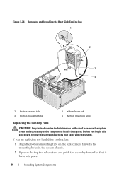
... two release tabs and guide the assembly forward so that it locks into place. 86 Installing System Components Removing and Installing the Heat Sink Cooling Fan 1 2 3 4 1 bottom release tab 3 bottom mounting tabs 2 side release tab 4 bottom mounting holes Replacing the Cooling...
... two release tabs and guide the assembly forward so that it locks into place. 86 Installing System Components Removing and Installing the Heat Sink Cooling Fan 1 2 3 4 1 bottom release tab 3 bottom mounting tabs 2 side release tab 4 bottom mounting holes Replacing the Cooling...

Hardware Owner's Manual
Page 87
... chassis. Installing System Components 87 Align the slots on the side of the connector. Cabling the Heat Sink Cooling Fan 1 2 3 4 5 6 1 heat sink fan shroud 3 tab 5 heat sink fan 2 cable slot 4 fan connector cable 6 front drive bezel 5 Replace the heat sink and shroud assembly (see "Removing the Processor" on... page 79). Figure 3-25. If you are replacing the processor cooling fan: 1 Align the bottom mounting tabs on the replacement fan with the securing tabs on the chassis bracket mount. 2 Slide the fan toward the front panel until it snaps into place. 3 Secure the cables ...
... chassis. Installing System Components 87 Align the slots on the side of the connector. Cabling the Heat Sink Cooling Fan 1 2 3 4 5 6 1 heat sink fan shroud 3 tab 5 heat sink fan 2 cable slot 4 fan connector cable 6 front drive bezel 5 Replace the heat sink and shroud assembly (see "Removing the Processor" on... page 79). Figure 3-25. If you are replacing the processor cooling fan: 1 Align the bottom mounting tabs on the replacement fan with the securing tabs on the chassis bracket mount. 2 Slide the fan toward the front panel until it snaps into place. 3 Secure the cables ...
Hardware Owner's Manual
Page 88
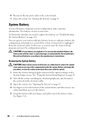
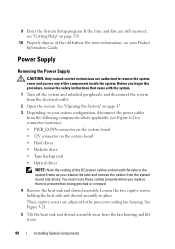
... maintains system configuration, date, and time information. You can last several years. See "Using the System Setup Program" on the System Setup screens. 6 Reconnect the fan power cable to remove the system cover and access any of the battery socket. See Figure 3-26. 88 Installing System Components See "Closing the System...
... maintains system configuration, date, and time information. You can last several years. See "Using the System Setup Program" on the System Setup screens. 6 Reconnect the fan power cable to remove the system cover and access any of the battery socket. See Figure 3-26. 88 Installing System Components See "Closing the System...
Hardware Owner's Manual
Page 90
... service technicians are adjacent to remove the system cover and access any of the old battery. These captive screws are authorized to the processor cooling fan housing. See "Opening the System" on page 47. 3 Depending on the system board • Hard drives • Diskette drive • Tape backup unit • Optical... two captive screws holding the heat sink and shroud assembly in the system frame as you release the tabs and remove the cables from the fan housing and lift it out. 90 Installing System Components
... service technicians are adjacent to remove the system cover and access any of the old battery. These captive screws are authorized to the processor cooling fan housing. See "Opening the System" on page 47. 3 Depending on the system board • Hard drives • Diskette drive • Tape backup unit • Optical... two captive screws holding the heat sink and shroud assembly in the system frame as you release the tabs and remove the cables from the fan housing and lift it out. 90 Installing System Components
Hardware Owner's Manual
Page 94
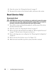
See "Removing the Cooling Fans" on page 79. Before you begin this procedure, review the safety instructions that came with the system. 1 Turn off the system and attached peripherals, and ... electrical outlet, and turn on page 47. 3 Remove the heat sink and shroud assembly. Do not remove the processor, however. 4 Remove the large processor cooling fan. See Figure 3-29. 6 Slide the bezel toward the top of the components inside the system.
See "Removing the Cooling Fans" on page 79. Before you begin this procedure, review the safety instructions that came with the system. 1 Turn off the system and attached peripherals, and ... electrical outlet, and turn on page 47. 3 Remove the heat sink and shroud assembly. Do not remove the processor, however. 4 Remove the large processor cooling fan. See Figure 3-29. 6 Slide the bezel toward the top of the components inside the system.
Hardware Owner's Manual
Page 95
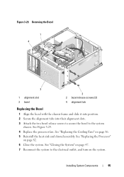
See "Replacing the Processor" on page 86. 5 Reinstall the heat sink and shroud assembly. Installing System Components 95 See Figure 3-29. 4 Replace the processor fan. See "Replacing the Cooling Fans" on page 82. 6 Close the system. See "Closing the System" on page 47. 7 Reconnect the system to the system chassis. Removing the Bezel...
See "Replacing the Processor" on page 86. 5 Reinstall the heat sink and shroud assembly. Installing System Components 95 See Figure 3-29. 4 Replace the processor fan. See "Replacing the Cooling Fans" on page 82. 6 Close the system. See "Closing the System" on page 47. 7 Reconnect the system to the system chassis. Removing the Bezel...

Hardware Owner's Manual
Page 96
... 79. See "Removing the Bezel" on page 47. 3 Remove the heat sink and shroud assembly. Do not remove the processor, however. 4 Remove the processor cooling fan. NOTICE: Carefully note the routing of each cable before you are authorized to re-route cables correctly. 6 Disconnect the I/O panel ribbon cable from the I/O panel...
... 79. See "Removing the Bezel" on page 47. 3 Remove the heat sink and shroud assembly. Do not remove the processor, however. 4 Remove the processor cooling fan. NOTICE: Carefully note the routing of each cable before you are authorized to re-route cables correctly. 6 Disconnect the I/O panel ribbon cable from the I/O panel...
Hardware Owner's Manual
Page 98
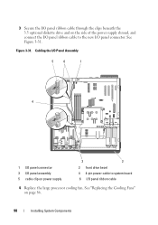
Figure 3-31. Cabling the I/O Panel Assembly 5 6 1 4 1 I/O panel connector 3 I/O panel assembly 5 cable clip on power supply 3 2 2 front drive bezel 4 4-pin power cable to the new I /O panel ribbon cable 4 Replace the large processor cooling fan. See Figure 3-31. See "Replacing the Cooling Fans" on page 86. 98 Installing System Components 3 Secure the I/O panel ribbon cable through the clips beneath the 3.5 optional diskette drive and on the side of the power supply shroud, and connect the I/O panel ribbon cable to system board 6 I /O panel connector.
Figure 3-31. Cabling the I/O Panel Assembly 5 6 1 4 1 I/O panel connector 3 I/O panel assembly 5 cable clip on power supply 3 2 2 front drive bezel 4 4-pin power cable to the new I /O panel ribbon cable 4 Replace the large processor cooling fan. See Figure 3-31. See "Replacing the Cooling Fans" on page 86. 98 Installing System Components 3 Secure the I/O panel ribbon cable through the clips beneath the 3.5 optional diskette drive and on the side of the power supply shroud, and connect the I/O panel ribbon cable to system board 6 I /O panel connector.
Hardware Owner's Manual
Page 99
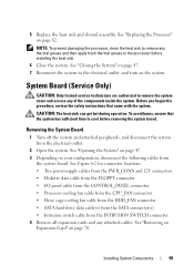
... 12V connectors • Diskette data cable from the FLOPPY connector • I/O panel cable from the CONTROL_PANEL connector • Processor cooling fan cable from the CPU_FAN connector • Drive cage cooling fan cable from the HDD_FAN connector • SATA hard-drive data cable(s) from the SATA connector(s) • Intrusion switch cable from the...
... 12V connectors • Diskette data cable from the FLOPPY connector • I/O panel cable from the CONTROL_PANEL connector • Processor cooling fan cable from the CPU_FAN connector • Drive cage cooling fan cable from the HDD_FAN connector • SATA hard-drive data cable(s) from the SATA connector(s) • Intrusion switch cable from the...


