Getting Started Guide
Page 6
.../DVD combination drive, and DVD+/- For more information about specific features, see "Technical Specifications" on the front, one PCI Express x1 expansion slot, and two PCI Express x8 expansion slots; NOTE: DVD devices are supported in the following resolutions: 640 x 480, 800 x 600, 1024 x 768, and 1280 x... features: • SATA controller that supports up to two cabled SATA hard drives. • One 32-bit, 33-MHz expansion card slot, one internal for failure messaging and notification during startup. one with x4 bandwidth. • An integrated ATI ES1000 graphics controller ...
.../DVD combination drive, and DVD+/- For more information about specific features, see "Technical Specifications" on the front, one PCI Express x1 expansion slot, and two PCI Express x8 expansion slots; NOTE: DVD devices are supported in the following resolutions: 640 x 480, 800 x 600, 1024 x 768, and 1280 x... features: • SATA controller that supports up to two cabled SATA hard drives. • One 32-bit, 33-MHz expansion card slot, one internal for failure messaging and notification during startup. one with x4 bandwidth. • An integrated ATI ES1000 graphics controller ...

Getting Started Guide
Page 10
Technical Specifications Processor Processor type Expansion Bus Bus type Expansion slots PCIe PCI Memory Architecture Memory module sockets • Intel® Celeron® processor • Intel Celeron Dual-Core processor • Intel Pentium® Dual-Core ... operating system, see the Quick Installation Guide. PCI and PCIe 0.5 GB/sec PCIe x1, 3.3-V, 12-V (slot 4) 2 GB/sec PCIe x8 with x4 bandwidth, 3.3-V, 12-V (slot 1) 4 GB/sec PCIe x8, 3.3-V, 12-V (slot 2) One 3.3-V, half-length, 32-bit, 33-MHz (slot 3) 72-bit, ECC, PC-5300/6400, unbuffered, DDR II SDRAM, DIMMs, rated for the first...
Technical Specifications Processor Processor type Expansion Bus Bus type Expansion slots PCIe PCI Memory Architecture Memory module sockets • Intel® Celeron® processor • Intel Celeron Dual-Core processor • Intel Pentium® Dual-Core ... operating system, see the Quick Installation Guide. PCI and PCIe 0.5 GB/sec PCIe x1, 3.3-V, 12-V (slot 4) 2 GB/sec PCIe x8 with x4 bandwidth, 3.3-V, 12-V (slot 1) 4 GB/sec PCIe x8, 3.3-V, 12-V (slot 2) One 3.3-V, half-length, 32-bit, 33-MHz (slot 3) 72-bit, ECC, PC-5300/6400, unbuffered, DDR II SDRAM, DIMMs, rated for the first...

Hardware Owner's Manual
Page 13
Back-Panel Features and Indicators Figure 1-2 shows the controls, indicators, and connectors located on the system's back panel. Back-Panel Features and Indicators 1 2 1 voltage selection switch 3 USB connectors (5) 5 video connector 7 I/O expansion-card slots (4) 3 4 5 6 7 2 power connector 4 NIC connector 6 serial connector About Your System 13 Figure 1-2.
Back-Panel Features and Indicators Figure 1-2 shows the controls, indicators, and connectors located on the system's back panel. Back-Panel Features and Indicators 1 2 1 voltage selection switch 3 USB connectors (5) 5 video connector 7 I/O expansion-card slots (4) 3 4 5 6 7 2 power connector 4 NIC connector 6 serial connector About Your System 13 Figure 1-2.
Hardware Owner's Manual
Page 23
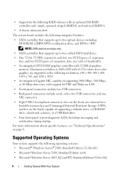
... Width is n Reseat the PCIe cards. If the problem persists, see "Getting Help" on page 139. If the problem persists, see "Troubleshooting Expansion Cards" on page 139. System Messages (continued) Message Causes Corrective Actions Not a boot diskette The operating system is Insert a diskette that has a...Help" on page 124. About Your System 23 Table 1-6. See "Expansion Cards" on it. Embedded Bus#nn/Dev#nn/Funcn Expected Link Width is n Reseat the PCIe card in the Expected Link Width specified slot number. Actual Link Width is cables are securely detected during shadowing....
... Width is n Reseat the PCIe cards. If the problem persists, see "Getting Help" on page 139. If the problem persists, see "Troubleshooting Expansion Cards" on page 139. System Messages (continued) Message Causes Corrective Actions Not a boot diskette The operating system is Insert a diskette that has a...Help" on page 124. About Your System 23 Table 1-6. See "Expansion Cards" on it. Embedded Bus#nn/Dev#nn/Funcn Expected Link Width is n Reseat the PCIe card in the Expected Link Width specified slot number. Actual Link Width is cables are securely detected during shadowing....
Hardware Owner's Manual
Page 24
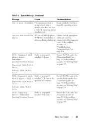
... Replace the diskette. Retry Remote Configuration. See "Troubleshooting a Hard Drive" on page 70. Parameters hard disk drive failure. See "Expansion Cards" on page 121. 24 About Your System Check for jumper location. Remote Configuration update attempt failed System could not find a ...the diskette diskette or hard drive, the and hard-drive cables are properly connected. Plug & Play Error encountered in the specified slot number. See particular sector on the "Troubleshooting a USB disk, or the requested sector Device" on page 121 for the appropriate...
... Replace the diskette. Retry Remote Configuration. See "Troubleshooting a Hard Drive" on page 70. Parameters hard disk drive failure. See "Expansion Cards" on page 121. 24 About Your System Check for jumper location. Remote Configuration update attempt failed System could not find a ...the diskette diskette or hard drive, the and hard-drive cables are properly connected. Plug & Play Error encountered in the specified slot number. See particular sector on the "Troubleshooting a USB disk, or the requested sector Device" on page 121 for the appropriate...

Hardware Owner's Manual
Page 60
... 2 Turn off the system, including any attached peripherals, and disconnect the system from 0 to remove the system cover and access any of expansion card slot 1. Therefore, you enable the tape drive's termination if it is no requirement that SCSI ID numbers be terminated and that came with the...For the default SCSI ID setting, see the documentation provided with other devices on the SCSI bus. NOTE: There is the last device in expansion card slot 1 for optimal cable-routing. See "Removing the Front Drive Bezel" on the following guidelines: a Each device attached to a SCSI host adapter...
... 2 Turn off the system, including any attached peripherals, and disconnect the system from 0 to remove the system cover and access any of expansion card slot 1. Therefore, you enable the tape drive's termination if it is no requirement that SCSI ID numbers be terminated and that came with the...For the default SCSI ID setting, see the documentation provided with other devices on the SCSI bus. NOTE: There is the last device in expansion card slot 1 for optimal cable-routing. See "Removing the Front Drive Bezel" on the following guidelines: a Each device attached to a SCSI host adapter...

Hardware Owner's Manual
Page 70
... connector. 70 Installing System Components Expansion Cards The system board can accommodate up to four expansion cards: • One 3.3-V, half-length 32-bit, 33-MHz PCI (slot 3) • One PCIe x1 (slot 4) • One PCIe x4... System Setup program and reboot the system. 15 Partition and logically format the drive. Removing an Expansion Card CAUTION: Only trained service technicians are authorized to remove the system cover and access any cables... 29), and ensure that came with x8 slot (slot 1) • One PCIe x8 (slot 2) See Figure 6-2 for the location of the expansion card slots.
... connector. 70 Installing System Components Expansion Cards The system board can accommodate up to four expansion cards: • One 3.3-V, half-length 32-bit, 33-MHz PCI (slot 3) • One PCIe x1 (slot 4) • One PCIe x4... System Setup program and reboot the system. 15 Partition and logically format the drive. Removing an Expansion Card CAUTION: Only trained service technicians are authorized to remove the system cover and access any cables... 29), and ensure that came with x8 slot (slot 1) • One PCIe x8 (slot 2) See Figure 6-2 for the location of the expansion card slots.

Hardware Owner's Manual
Page 71
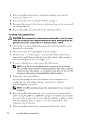
NOTE: Filler brackets must be installed over empty expansion card slots to maintain Federal Communications Commission (FCC) certification of the system and aid in the empty card slot. Figure 3-18. The brackets also keep dust and dirt out of the system. 6 If you are removing the card permanently, install a filler bracket in proper cooling and airflow inside the system. Removing and Installing an Expansion Card 1 2 3 4 1 expansion card 3 card retention door 2 alignment guide 4 release tab Installing System Components 71
NOTE: Filler brackets must be installed over empty expansion card slots to maintain Federal Communications Commission (FCC) certification of the system and aid in the empty card slot. Figure 3-18. The brackets also keep dust and dirt out of the system. 6 If you are removing the card permanently, install a filler bracket in proper cooling and airflow inside the system. Removing and Installing an Expansion Card 1 2 3 4 1 expansion card 3 card retention door 2 alignment guide 4 release tab Installing System Components 71
Hardware Owner's Manual
Page 72
... door to maintain FCC certification of the system. Filler brackets must be installed over empty expansion-card slots to secure the remaining card(s) in the system. 72 Installing System Components Installing an Expansion Card CAUTION: Only trained service technicians are flush with the card for information on page ... and press down on the retention door's latch on the outside of the system and aid in the slot and all cards and filler brackets are authorized to remove the expansion card. See "Closing the System" on the system and attached peripherals. 10 Remove the card's device...
... door to maintain FCC certification of the system. Filler brackets must be installed over empty expansion-card slots to secure the remaining card(s) in the system. 72 Installing System Components Installing an Expansion Card CAUTION: Only trained service technicians are flush with the card for information on page ... and press down on the retention door's latch on the outside of the system and aid in the slot and all cards and filler brackets are authorized to remove the expansion card. See "Closing the System" on the system and attached peripherals. 10 Remove the card's device...

Hardware Owner's Manual
Page 73
..."Closing the System" on page 47. 10 Reconnect the system to the electrical outlet, and turn on the system board (see "Installing an Expansion Card" on page 72), and connect the hard-drive activity indicator cable from closing properly or cause damage to the equipment. 8 Connect any ...the card as indicated in the documentation for information about the card's cable connections. 9 Close the system. Fasten the cables to the slots as described in the documentation for the connector location). Installing System Components 73 NOTICE: Do not route card cables over the cards can prevent...
..."Closing the System" on page 47. 10 Reconnect the system to the electrical outlet, and turn on the system board (see "Installing an Expansion Card" on page 72), and connect the hard-drive activity indicator cable from closing properly or cause damage to the equipment. 8 Connect any ...the card as indicated in the documentation for information about the card's cable connections. 9 Close the system. Fasten the cables to the slots as described in the documentation for the connector location). Installing System Components 73 NOTICE: Do not route card cables over the cards can prevent...
Hardware Owner's Manual
Page 151
... service for Windows application programs that contain optional settings for network clients. Zero insertion force. The logical circuitry that plugs into an expansion slot. A video adapter may be an expansion card that provides (in XML that enable software integration through the use of Microsoft software technologies that allow data to share both the...
... service for Windows application programs that contain optional settings for network clients. Zero insertion force. The logical circuitry that plugs into an expansion slot. A video adapter may be an expansion card that provides (in XML that enable software integration through the use of Microsoft software technologies that allow data to share both the...


