Hardware Owner's Manual
Page 5
... Addressing Memory With 8-GB Configurations (Microsoft® Windows® Operating System Only 76 Removing a Memory Module 77 Installing a Memory Module 77 Microprocessor 79 Removing the Processor 79 Replacing the Processor 82 Cooling Fans 83 Removing the Cooling Fans 83 Replacing the Cooling...
... Addressing Memory With 8-GB Configurations (Microsoft® Windows® Operating System Only 76 Removing a Memory Module 77 Installing a Memory Module 77 Microprocessor 79 Removing the Processor 79 Replacing the Processor 82 Cooling Fans 83 Removing the Cooling Fans 83 Replacing the Cooling...
Hardware Owner's Manual
Page 46
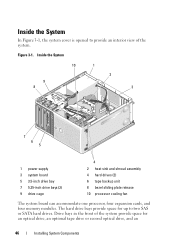
... 7 5.25-inch drive bays (2) 9 drive cage 4 2 heat sink and shroud assembly 4 hard drives (2) 6 tape backup unit 8 bezel sliding plate release 10 processor cooling fan The system board can accommodate one processor, four expansion cards, and four memory modules. Drive bays in the front of the system. Inside the System In Figure 3-1, the system...
... 7 5.25-inch drive bays (2) 9 drive cage 4 2 heat sink and shroud assembly 4 hard drives (2) 6 tape backup unit 8 bezel sliding plate release 10 processor cooling fan The system board can accommodate one processor, four expansion cards, and four memory modules. Drive bays in the front of the system. Inside the System In Figure 3-1, the system...

Hardware Owner's Manual
Page 80
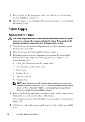
...lift it aside. 4 Using a #2 Phillips screwdriver, loosen the two captive screws holding the heat sink and shroud assembly in place. CAUTION: The processor and heat sink can get very hot during normal operation. See "Opening the System" on page 47. 3 Detach the diskette cable that they ...have had sufficient time to the processor cooling fan housing. These captive screws are adjacent to cool before you touch them. 1 Turn off the system and attached peripherals, and disconnect the ...
...lift it aside. 4 Using a #2 Phillips screwdriver, loosen the two captive screws holding the heat sink and shroud assembly in place. CAUTION: The processor and heat sink can get very hot during normal operation. See "Opening the System" on page 47. 3 Detach the diskette cable that they ...have had sufficient time to the processor cooling fan housing. These captive screws are adjacent to cool before you touch them. 1 Turn off the system and attached peripherals, and disconnect the ...

Hardware Owner's Manual
Page 83
.... Applying new thermal grease is critical to remove the system cover and access any of the cooling fan assembly. Cooling Fans The system contains two cooling fans, one for the processor and one for the card cage. Each contains a shroud that is part of the components inside ... assembly to the electrical outlet, and turn on the system and attached peripherals. Removing the Cooling Fans CAUTION: Only trained service technicians are removing the larger processor cooling fan, you apply new thermal grease. Before you begin this procedure, review the safety instructions that you...
.... Applying new thermal grease is critical to remove the system cover and access any of the cooling fan assembly. Cooling Fans The system contains two cooling fans, one for the processor and one for the card cage. Each contains a shroud that is part of the components inside ... assembly to the electrical outlet, and turn on the system and attached peripherals. Removing the Cooling Fans CAUTION: Only trained service technicians are removing the larger processor cooling fan, you apply new thermal grease. Before you begin this procedure, review the safety instructions that you...

Hardware Owner's Manual
Page 84
... shift it forward to guide the bottom mounting tabs out of the fan cage that attaches the processor cooling fan to the chassis bracket mount. d Slide the fan toward the back panel and lift the fan out. 84 Installing System Components 3 Disconnect the fan's power cable from the system board. NOTE: The SAS hard drive cooling...
... shift it forward to guide the bottom mounting tabs out of the fan cage that attaches the processor cooling fan to the chassis bracket mount. d Slide the fan toward the back panel and lift the fan out. 84 Installing System Components 3 Disconnect the fan's power cable from the system board. NOTE: The SAS hard drive cooling...

Hardware Owner's Manual
Page 87
... the system board. See Figure 3-25. 4 Attach the fan cable to manage unwanted slack. Cabling the Heat Sink Cooling Fan 1 2 3 4 5 6 1 heat sink fan shroud 3 tab 5 heat sink fan 2 cable slot 4 fan connector cable 6 front drive bezel 5 Replace the heat sink and shroud assembly (see "Removing the Processor" on the side of the connector. Align the slots...
... the system board. See Figure 3-25. 4 Attach the fan cable to manage unwanted slack. Cabling the Heat Sink Cooling Fan 1 2 3 4 5 6 1 heat sink fan shroud 3 tab 5 heat sink fan 2 cable slot 4 fan connector cable 6 front drive bezel 5 Replace the heat sink and shroud assembly (see "Removing the Processor" on the side of the connector. Align the slots...
Hardware Owner's Manual
Page 90
... Information Guide. These captive screws are authorized to remove the system cover and access any of the old battery. Before you replace them to the processor cooling fan housing. For more information, see Figure 6-2 for connector locations): • PWR_CONN connector on the system board • 12V connector on page 139. 10 Properly... two captive screws holding the heat sink and shroud assembly in the system frame as you release the tabs and remove the cables from the fan housing and lift it out. 90 Installing System Components
... Information Guide. These captive screws are authorized to remove the system cover and access any of the old battery. Before you replace them to the processor cooling fan housing. For more information, see Figure 6-2 for connector locations): • PWR_CONN connector on the system board • 12V connector on page 139. 10 Properly... two captive screws holding the heat sink and shroud assembly in the system frame as you release the tabs and remove the cables from the fan housing and lift it out. 90 Installing System Components
Hardware Owner's Manual
Page 94
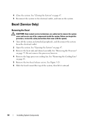
...system to remove the system cover and access any of the system, then lift it outward. 94 Installing System Components See "Removing the Processor" on the system. Before you begin this procedure, review the safety instructions that came with the system. 1 Turn off the system and... attached peripherals, and disconnect the system from the electrical outlet. 2 Open the system. Do not remove the processor, however. 4 Remove the large processor cooling fan. See "Removing the Cooling Fans" on page 47. 3 Remove the heat sink and shroud assembly. Bezel (Service Only) Removing the Bezel CAUTION...
...system to remove the system cover and access any of the system, then lift it outward. 94 Installing System Components See "Removing the Processor" on the system. Before you begin this procedure, review the safety instructions that came with the system. 1 Turn off the system and... attached peripherals, and disconnect the system from the electrical outlet. 2 Open the system. Do not remove the processor, however. 4 Remove the large processor cooling fan. See "Removing the Cooling Fans" on page 47. 3 Remove the heat sink and shroud assembly. Bezel (Service Only) Removing the Bezel CAUTION...
Hardware Owner's Manual
Page 95
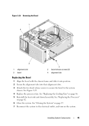
See Figure 3-29. 4 Replace the processor fan. See "Replacing the Processor" on page 86. 5 Reinstall the heat sink and shroud assembly. See "Replacing the Cooling Fans" on page 82. 6 Close the system. See "Closing the System" on page 47. 7 Reconnect the system to the system chassis. Removing the Bezel 1 4 3 1 alignment slot 3 ...
See Figure 3-29. 4 Replace the processor fan. See "Replacing the Processor" on page 86. 5 Reinstall the heat sink and shroud assembly. See "Replacing the Cooling Fans" on page 82. 6 Close the system. See "Closing the System" on page 47. 7 Reconnect the system to the system chassis. Removing the Bezel 1 4 3 1 alignment slot 3 ...

Hardware Owner's Manual
Page 96
See "Opening the System" on page 79. See "Removing the Processor" on page 47. 3 Remove the heat sink and shroud assembly. NOTICE: Carefully note the routing of each cable before you are authorized to the front chassis. See "Removing the Cooling Fans" on page 94. See Figure 3-30. 8 Lift the I /O Panel Assembly 1 Turn... I/O panel ribbon cable from the electrical outlet. 2 Open the system. See "Removing the Bezel" on page 83. 5 Remove the front bezel. Do not remove the processor, however. 4 Remove the processor cooling fan.
See "Opening the System" on page 79. See "Removing the Processor" on page 47. 3 Remove the heat sink and shroud assembly. NOTICE: Carefully note the routing of each cable before you are authorized to the front chassis. See "Removing the Cooling Fans" on page 94. See Figure 3-30. 8 Lift the I /O Panel Assembly 1 Turn... I/O panel ribbon cable from the electrical outlet. 2 Open the system. See "Removing the Bezel" on page 83. 5 Remove the front bezel. Do not remove the processor, however. 4 Remove the processor cooling fan.
Hardware Owner's Manual
Page 98
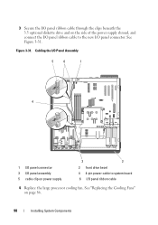
See Figure 3-31. See "Replacing the Cooling Fans" on power supply 3 2 2 front drive bezel 4 4-pin power cable to the new I /O panel assembly 5 cable clip on page 86. 98 Installing System Components Figure 3-31. Cabling the I/O Panel Assembly 5 6 1 4 1 I/O panel connector 3 I /O panel connector. 3 Secure the I/O panel ribbon cable through the clips beneath the 3.5 optional diskette drive and on the side of the power supply shroud, and connect the I/O panel ribbon cable to system board 6 I/O panel ribbon cable 4 Replace the large processor cooling fan.
See Figure 3-31. See "Replacing the Cooling Fans" on power supply 3 2 2 front drive bezel 4 4-pin power cable to the new I /O panel assembly 5 cable clip on page 86. 98 Installing System Components Figure 3-31. Cabling the I/O Panel Assembly 5 6 1 4 1 I/O panel connector 3 I /O panel connector. 3 Secure the I/O panel ribbon cable through the clips beneath the 3.5 optional diskette drive and on the side of the power supply shroud, and connect the I/O panel ribbon cable to system board 6 I/O panel ribbon cable 4 Replace the large processor cooling fan.
Hardware Owner's Manual
Page 99
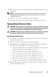
... (Service Only) CAUTION: Only trained service technicians are authorized to the electrical outlet, and turn on the system. See "Replacing the Processor" on page 70. See "Closing the System" on your configuration, disconnect the following cables from the electrical outlet. 2 Open the ...8226; Diskette data cable from the FLOPPY connector • I/O panel cable from the CONTROL_PANEL connector • Processor cooling fan cable from the CPU_FAN connector • Drive cage cooling fan cable from the HDD_FAN connector • SATA hard-drive data cable(s) from the SATA connector(s) •...
... (Service Only) CAUTION: Only trained service technicians are authorized to the electrical outlet, and turn on the system. See "Replacing the Processor" on page 70. See "Closing the System" on your configuration, disconnect the following cables from the electrical outlet. 2 Open the ...8226; Diskette data cable from the FLOPPY connector • I/O panel cable from the CONTROL_PANEL connector • Processor cooling fan cable from the CPU_FAN connector • Drive cage cooling fan cable from the HDD_FAN connector • SATA hard-drive data cable(s) from the SATA connector(s) •...

Hardware Owner's Manual
Page 101
... 12V connectors • If applicable, diskette data cable to the FLOPPY connector • I/O panel cable to the CONTROL_PANEL connector • Processor cooling fan cable to the CPU_FAN connector • Drive cage cooling fan cable to the HDD_FAN connector • SATA hard-drive data cable(s) to the electrical outlet, and turn on the system...
... 12V connectors • If applicable, diskette data cable to the FLOPPY connector • I/O panel cable to the CONTROL_PANEL connector • Processor cooling fan cable to the CPU_FAN connector • Drive cage cooling fan cable to the HDD_FAN connector • SATA hard-drive data cable(s) to the electrical outlet, and turn on the system...
Hardware Owner's Manual
Page 112
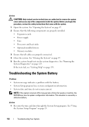
... system diagnostics. See "Opening the System" on page 47. 2 Ensure that the following components are properly installed: • Expansion cards • Power supply • Fans • Processors and heat sinks • Optional installed drivers • Memory modules 3 Ensure that came with the battery. • System Setup program loses system configuration information. •...
... system diagnostics. See "Opening the System" on page 47. 2 Ensure that the following components are properly installed: • Expansion cards • Power supply • Fans • Processors and heat sinks • Optional installed drivers • Memory modules 3 Ensure that came with the battery. • System Setup program loses system configuration information. •...

Hardware Owner's Manual
Page 136
... x4 (x8 slot) PCIe x8 32-bit, 33-MHz PCI PCIe x1 diskette drive system board jumpers internal USB key drive cage fan processor fan auxiliary hard drive LED battery socket processor 12V power connector memory module memory module memory module memory module Disabling a Forgotten Password The password jumper on the system board enables...
... x4 (x8 slot) PCIe x8 32-bit, 33-MHz PCI PCIe x1 diskette drive system board jumpers internal USB key drive cage fan processor fan auxiliary hard drive LED battery socket processor 12V power connector memory module memory module memory module memory module Disabling a Forgotten Password The password jumper on the system board enables...
Hardware Owner's Manual
Page 141
... your system documents. American Standard Code for developing technology standards in the U.S. backup - A battery that includes power supplies and fans. blade - Ampere(s). Advanced Configuration and Power Interface. Applications run from your system. As a precaution, back up files from ... management. backup battery - Baseboard management controller. For example, one beep, followed by your system's speaker. A module that contains a processor, memory, and a hard drive. ACPI - Before making a change to help you perform a specific task or series of three beeps...
... your system documents. American Standard Code for developing technology standards in the U.S. backup - A battery that includes power supplies and fans. blade - Ampere(s). Advanced Configuration and Power Interface. Applications run from your system. As a precaution, back up files from ... management. backup battery - Baseboard management controller. For example, one beep, followed by your system's speaker. A module that contains a processor, memory, and a hard drive. ACPI - Before making a change to help you perform a specific task or series of three beeps...
Hardware Owner's Manual
Page 156
... 38 working with, 42 startup accessing system features, 10 support contacting Dell, 139 See hard drive. SATA hard drive. POST accessing system features, 10 power supply installing, 92 removing, 90 replacing, 92 troubleshooting, 113 processor installing, 82 removing, 79 replacing, 82 troubleshooting, 126 R recommended ...tape drive, 57 156 Index replacing bezel, 95 chassis intrusion switch, 93 cooling fans, 86 diskette drive, 54 expansion cards, 72 front drive bezel, 49 I/O panel, 97 memory, 77 power supply, 92 processor, 82 system board, 100 S safety, 103 SAS controller card installing, 73 ...
... 38 working with, 42 startup accessing system features, 10 support contacting Dell, 139 See hard drive. SATA hard drive. POST accessing system features, 10 power supply installing, 92 removing, 90 replacing, 92 troubleshooting, 113 processor installing, 82 removing, 79 replacing, 82 troubleshooting, 126 R recommended ...tape drive, 57 156 Index replacing bezel, 95 chassis intrusion switch, 93 cooling fans, 86 diskette drive, 54 expansion cards, 72 front drive bezel, 49 I/O panel, 97 memory, 77 power supply, 92 processor, 82 system board, 100 S safety, 103 SAS controller card installing, 73 ...


