Hardware Owner's Manual
Page 3
Contents 1 About Your System 9 Other Information You May Need 9 Accessing System Features During Startup 10 Front-Panel Features and Indicators 11 Back-Panel Features and Indicators 13 Connecting External Devices 14 NIC Indicator Codes 14 Power Supply Indicators 15 Diagnostic Lights 16 System Messages 18 Warning Messages 27 Diagnostics Messages 27 Alert Messages 27 2 Using the System Setup Program 29 Entering the System Setup Program 29 Responding to Error Messages 29 Using the System Setup Program 30 Contents 3
Contents 1 About Your System 9 Other Information You May Need 9 Accessing System Features During Startup 10 Front-Panel Features and Indicators 11 Back-Panel Features and Indicators 13 Connecting External Devices 14 NIC Indicator Codes 14 Power Supply Indicators 15 Diagnostic Lights 16 System Messages 18 Warning Messages 27 Diagnostics Messages 27 Alert Messages 27 2 Using the System Setup Program 29 Entering the System Setup Program 29 Responding to Error Messages 29 Using the System Setup Program 30 Contents 3

Hardware Owner's Manual
Page 12
... low power state. Holds an optional optical or tape backup unit drive. Front-Panel Components (continued) Item Component Icon 2 power button 3 power light 4 flex bay 5 lower 5.25-inch drive bay 6 upper 5.25-inch drive bay Description The power button controls the DC power supply output to... power is running an ACPI-compliant operating system, the system performs a graceful shutdown before Power-On Self Test (POST). Steady green - See "Diagnostic Lights" on . Blinking amber - Holds an optical drive. 12 About Your System The system is off. NOTE: If you turn off the system ...
... low power state. Holds an optional optical or tape backup unit drive. Front-Panel Components (continued) Item Component Icon 2 power button 3 power light 4 flex bay 5 lower 5.25-inch drive bay 6 upper 5.25-inch drive bay Description The power button controls the DC power supply output to... power is running an ACPI-compliant operating system, the system performs a graceful shutdown before Power-On Self Test (POST). Steady green - See "Diagnostic Lights" on . Blinking amber - Holds an optical drive. 12 About Your System The system is off. NOTE: If you turn off the system ...
Hardware Owner's Manual
Page 16
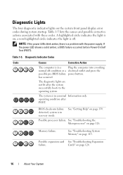
... on the system front panel display error codes during system startup. Diagnostic Lights The four diagnostic indicator lights on page 124. 16 About Your System a non-highlighted circle indicates the light is in recovery mode. The diagnostic lights are not lit after POST. system is off condition or a electrical.... operating condition after the system successfully boots to the operating system. A highlighted circle indicates the light is a problem with these codes. BIOS checksum failure detected; Possible processor failure. See "Troubleshooting System Memory" on ;
... on the system front panel display error codes during system startup. Diagnostic Lights The four diagnostic indicator lights on page 124. 16 About Your System a non-highlighted circle indicates the light is in recovery mode. The diagnostic lights are not lit after POST. system is off condition or a electrical.... operating condition after the system successfully boots to the operating system. A highlighted circle indicates the light is a problem with these codes. BIOS checksum failure detected; Possible processor failure. See "Troubleshooting System Memory" on ;
Hardware Owner's Manual
Page 103
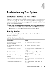
...the system. Start-Up Routine Indications Look/listen for the indications described in Table 4-1. See "Troubleshooting a Diskette Drive" on the system diagnostic indicators. Start-Up Routine Look and listen during the system's start-up routine for : A code displayed on page 117. See ..., you begin this guide and elsewhere in your system documentation. The keyboard indicators. The USB CD drive activity indicator. Action See "Diagnostic Lights" on page 119. Table 4-1. The monitor's power indicator. See "System Messages" on page 18. The hard-drive activity indicator....
...the system. Start-Up Routine Indications Look/listen for the indications described in Table 4-1. See "Troubleshooting a Diskette Drive" on the system diagnostic indicators. Start-Up Routine Look and listen during the system's start-up routine for : A code displayed on page 117. See ..., you begin this guide and elsewhere in your system documentation. The keyboard indicators. The USB CD drive activity indicator. Action See "Diagnostic Lights" on page 119. Table 4-1. The monitor's power indicator. See "System Messages" on page 18. The hard-drive activity indicator....
Hardware Owner's Manual
Page 110
... NIC card. 3 Ensure that the NICs, hubs, and switches on page 14. • If the link indicator does not light, check all set to the same data transmission speed. See "Using Dell PowerEdge Diagnostics" on page 129. 2 Check the appropriate indicator on the switch or hub. See "Using the System Setup Program" on page...
... NIC card. 3 Ensure that the NICs, hubs, and switches on page 14. • If the link indicator does not light, check all set to the same data transmission speed. See "Using Dell PowerEdge Diagnostics" on page 129. 2 Check the appropriate indicator on the switch or hub. See "Using the System Setup Program" on page...


