Getting Started Guide
Page 5
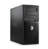
... Intel Pentium® Dual-Core processor - Getting Started With Your System 3 Intel Celeron Dual-Core processor - or 800-MHz DDR II SDRAM memory, upgradable to two internal 3.5-inch SATA hard drives with a SAS controller card • One 3.5-inch peripheral drive bay for the optional diskette ... It also provides information about other documents you may differ by installing 512-MB, 1-GB, or 2-GB unbuffered ECC memory modules in the four memory module sockets on the system board; Quad-Core Intel Xeon processor NOTE: Processor availability may need when setting up your ...
... Intel Pentium® Dual-Core processor - Getting Started With Your System 3 Intel Celeron Dual-Core processor - or 800-MHz DDR II SDRAM memory, upgradable to two internal 3.5-inch SATA hard drives with a SAS controller card • One 3.5-inch peripheral drive bay for the optional diskette ... It also provides information about other documents you may differ by installing 512-MB, 1-GB, or 2-GB unbuffered ECC memory modules in the four memory module sockets on the system board; Quad-Core Intel Xeon processor NOTE: Processor availability may need when setting up your ...
Getting Started Guide
Page 6
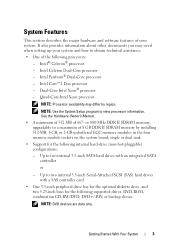
... and Unmanaged Internal Persistent Storage (UIPS), and five on the back) capable of graphics memory. one internal for the following resolutions: 640 x 480, 800 x 600, 1024 x 768, and 1280 x 1024. • An integrated Gigabit NIC, capable of supporting 1000-Mbps, ...
... and Unmanaged Internal Persistent Storage (UIPS), and five on the back) capable of graphics memory. one internal for the following resolutions: 640 x 480, 800 x 600, 1024 x 768, and 1280 x 1024. • An integrated Gigabit NIC, capable of supporting 1000-Mbps, ...

Getting Started Guide
Page 10
... is installed before installing hardware or software not purchased with your system. Technical Specifications Processor Processor type Expansion Bus Bus type Expansion slots PCIe PCI Memory Architecture Memory module sockets • Intel® Celeron® processor • Intel Celeron Dual-Core processor • Intel Pentium® Dual-Core processor • Intel Core...
... is installed before installing hardware or software not purchased with your system. Technical Specifications Processor Processor type Expansion Bus Bus type Expansion slots PCIe PCI Memory Architecture Memory module sockets • Intel® Celeron® processor • Intel Celeron Dual-Core processor • Intel Pentium® Dual-Core processor • Intel Core...
Getting Started Guide
Page 11
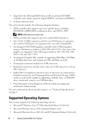
... card one RJ-45 (for Broadcom Gigabit LOM) 9-pin, DTE, 16550-compatible five 4-pin, USB 2.0-compliant 15-pin VGA Getting Started With Your System 9 Memory (continued) Memory module capacities Minimum RAM Maximum RAM Drives Hard Drives Diskette drive Optical drives Backup device Flash drive Connectors Back NIC Serial USB Video 512 MB...
... card one RJ-45 (for Broadcom Gigabit LOM) 9-pin, DTE, 16550-compatible five 4-pin, USB 2.0-compliant 15-pin VGA Getting Started With Your System 9 Memory (continued) Memory module capacities Minimum RAM Maximum RAM Drives Hard Drives Diskette drive Optical drives Backup device Flash drive Connectors Back NIC Serial USB Video 512 MB...

Getting Started Guide
Page 12
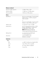
Connectors (continued) Front USB Internally accessible SATA channels USB key (for memory key) Video Video type Video memory Power AC power supply (per power supply) Wattage Voltage Heat dissipation CMOS Backup Battery Physical Height Width Depth Weight (maximum configuration) one 4-pin USB 2.0-compliant (...
Connectors (continued) Front USB Internally accessible SATA channels USB key (for memory key) Video Video type Video memory Power AC power supply (per power supply) Wattage Voltage Heat dissipation CMOS Backup Battery Physical Height Width Depth Weight (maximum configuration) one 4-pin USB 2.0-compliant (...

Hardware Owner's Manual
Page 4
System Setup Options 30 Main Screen 30 Memory Information Screen 33 CPU Information Screen 33 SATA Configuration Screen 34 Integrated Devices Screen 35 Console Redirection Screen 36 System Security Screen 36 Exit Screen ...
System Setup Options 30 Main Screen 30 Memory Information Screen 33 CPU Information Screen 33 SATA Configuration Screen 34 Integrated Devices Screen 35 Console Redirection Screen 36 System Security Screen 36 Exit Screen ...
Hardware Owner's Manual
Page 5
... Expansion Card 70 Installing an Expansion Card 72 SAS Controller Expansion Card 73 Memory 75 Memory Module Upgrade Kits 75 Memory Module Installation Guidelines 75 Addressing Memory With 8-GB Configurations (Microsoft® Windows® Operating System Only 76 Removing a Memory Module 77 Installing a Memory Module 77 Microprocessor 79 Removing the Processor 79 Replacing the Processor 82...
... Expansion Card 70 Installing an Expansion Card 72 SAS Controller Expansion Card 73 Memory 75 Memory Module Upgrade Kits 75 Memory Module Installation Guidelines 75 Addressing Memory With 8-GB Configurations (Microsoft® Windows® Operating System Only 76 Removing a Memory Module 77 Installing a Memory Module 77 Microprocessor 79 Removing the Processor 79 Replacing the Processor 82...
Hardware Owner's Manual
Page 7
... a Fan 114 Troubleshooting System Memory 115 Troubleshooting a Diskette Drive 117 Troubleshooting an Optical Drive 119 Troubleshooting an External SCSI Tape Drive . . . . . 120 Troubleshooting a Hard Drive 121 Troubleshooting a SAS or SAS RAID Controller . . . . 123 Troubleshooting Expansion Cards 124 Troubleshooting the Microprocessor 126 5 Running the System Diagnostics 129 Using Dell PowerEdge Diagnostics 129 System Diagnostics...
... a Fan 114 Troubleshooting System Memory 115 Troubleshooting a Diskette Drive 117 Troubleshooting an Optical Drive 119 Troubleshooting an External SCSI Tape Drive . . . . . 120 Troubleshooting a Hard Drive 121 Troubleshooting a SAS or SAS RAID Controller . . . . 123 Troubleshooting Expansion Cards 124 Troubleshooting the Microprocessor 126 5 Running the System Diagnostics 129 Using Dell PowerEdge Diagnostics 129 System Diagnostics...
Hardware Owner's Manual
Page 16
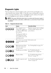
... causes and possible corrective actions associated with the power supply. Table 1-5. The system is in a normal Information only. system is in recovery mode. Memory failure. See "Troubleshooting System Memory" on page 139. BIOS checksum failure detected; has occurred. Possible expansion card See "Troubleshooting Expansion failure. A highlighted circle indicates the light is off...
... causes and possible corrective actions associated with the power supply. Table 1-5. The system is in a normal Information only. system is in recovery mode. Memory failure. See "Troubleshooting System Memory" on page 139. BIOS checksum failure detected; has occurred. Possible expansion card See "Troubleshooting Expansion failure. A highlighted circle indicates the light is off...
Hardware Owner's Manual
Page 17
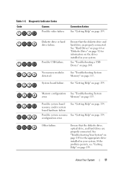
... failure. Table 1-5. See "Troubleshooting a USB Device" on page 103 for information on page 139. See "Troubleshooting System Memory" on page 115. Memory" on page 115. configuration error. Diskette drive or hard drive failure. Ensure that the diskette drive, optical drive, and... hard drives are properly connected. Memory configuration See "Troubleshooting System error. Possible system resource See "Getting Help" on page 139. If the problem persists, see ...
... failure. Table 1-5. See "Troubleshooting a USB Device" on page 103 for information on page 139. See "Troubleshooting System Memory" on page 115. Memory" on page 115. configuration error. Diskette drive or hard drive failure. Ensure that the diskette drive, optical drive, and... hard drives are properly connected. Memory configuration See "Troubleshooting System error. Possible system resource See "Getting Help" on page 139. If the problem persists, see ...
Hardware Owner's Manual
Page 19
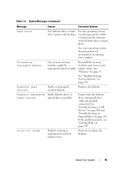
...operating system documentation for information on page 139. Diskette subsystem Faulty diskette drive or reset failed optical drive controller. Decreasing available memory One or more memory Reinstall the memory modules might be modules and, if necessary, improperly seated or faulty. replace them. Diskette read the data. Drive not ready...or improperly inserted diskette. Ensure that the diskette drive and optical drive cables are properly connected. Table 1-6. See "Troubleshooting System Memory" on page 115. Replace the diskette. Reinsert or replace the diskette.
...operating system documentation for information on page 139. Diskette subsystem Faulty diskette drive or reset failed optical drive controller. Decreasing available memory One or more memory Reinstall the memory modules might be modules and, if necessary, improperly seated or faulty. replace them. Diskette read the data. Drive not ready...or improperly inserted diskette. Ensure that the diskette drive and optical drive cables are properly connected. Table 1-6. See "Troubleshooting System Memory" on page 115. Replace the diskette. Reinsert or replace the diskette.

Hardware Owner's Manual
Page 20
..." on failure (faulty system board). faulty keyboard controller. If the problem persists, see "Getting Help" on page 75. See "Memory Module Installation Guidelines" on page 139. 20 About Your System General failure The operating system is usually followed by specific information. The installed... memory modules are securely attached to correct connectors. Table 1-6. This message is unable to resolve the problem. Keyboard data line failure ...
..." on failure (faulty system board). faulty keyboard controller. If the problem persists, see "Getting Help" on page 75. See "Memory Module Installation Guidelines" on page 139. 20 About Your System General failure The operating system is usually followed by specific information. The installed... memory modules are securely attached to correct connectors. Table 1-6. This message is unable to resolve the problem. Keyboard data line failure ...

Hardware Owner's Manual
Page 21
Table 1-6. Faulty system board. If the problem persists, the system board is incorrectly detected configured. Memory address line Faulty or improperly Ensure that all memory failure at address, installed memory modules, modules are properly read value expecting value Memory tests terminated by keystroke The spacebar was pressed Information only. installed. If the problem persists, see...
Table 1-6. Faulty system board. If the problem persists, the system board is incorrectly detected configured. Memory address line Faulty or improperly Ensure that all memory failure at address, installed memory modules, modules are properly read value expecting value Memory tests terminated by keystroke The spacebar was pressed Information only. installed. If the problem persists, see...
Hardware Owner's Manual
Page 25
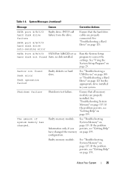
... on page 115. Ensure that the hard drive cables are properly installed. The amount of system memory has changed the memory configuration. Faulty memory module. See "Troubleshooting System Memory" on page 121 for the appropriate drive installed in your system. If the problem persists, see...Getting Help" on page 139. If the problem persists, see "Getting Help" on page 121. Shutdown failure Shutdown test failure. Faulty memory module. System Messages (continued) Message Causes Corrective Actions SATA port A/B/C/D hard disk drive failure Faulty drive. See "Troubleshooting a Hard ...
... on page 115. Ensure that the hard drive cables are properly installed. The amount of system memory has changed the memory configuration. Faulty memory module. See "Troubleshooting System Memory" on page 121 for the appropriate drive installed in your system. If the problem persists, see...Getting Help" on page 139. If the problem persists, see "Getting Help" on page 121. Shutdown failure Shutdown test failure. Faulty memory module. System Messages (continued) Message Causes Corrective Actions SATA port A/B/C/D hard disk drive failure Faulty drive. See "Troubleshooting a Hard ...
Hardware Owner's Manual
Page 26
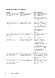
... 0 Micro code update failed. See "Using the System Setup Program" on page 139. If the problem persists, see "Troubleshooting System Memory" on page 75. See "Getting Help" on page 139. See "Troubleshooting the System Battery" on the boot hard drive. Utility...came with your system. System Messages (continued) Message Causes Corrective Actions Time-of -day not set Incorrect Time or Date - See "Memory Module Installation Guidelines" on page 115. Warning! faulty system program battery. Table 1-6. faulty stopped system board. Time-of -day clock Faulty...
... 0 Micro code update failed. See "Using the System Setup Program" on page 139. If the problem persists, see "Troubleshooting System Memory" on page 75. See "Getting Help" on page 139. See "Troubleshooting the System Battery" on the boot hard drive. Utility...came with your system. System Messages (continued) Message Causes Corrective Actions Time-of -day not set Incorrect Time or Date - See "Memory Module Installation Guidelines" on page 115. Warning! faulty system program battery. Table 1-6. faulty stopped system board. Time-of -day clock Faulty...

Hardware Owner's Manual
Page 29
... to: • Change the system configuration stored in NVRAM after you see the documentation that accompanied your system configuration and optional settings. NOTE: After installing a memory upgrade, it is booting, make a note of the message and suggestions for example, the time or date • Enable or disable integrated devices • Correct...
... to: • Change the system configuration stored in NVRAM after you see the documentation that accompanied your system configuration and optional settings. NOTE: After installing a memory upgrade, it is booting, make a note of the message and suggestions for example, the time or date • Enable or disable integrated devices • Correct...

Hardware Owner's Manual
Page 31
Figure 2-1. Resets the date on the system's internal clock. System Setup Program Options Option System Time System Date Memory Information CPU Information SATA Configuration Description Resets the time on the system's internal calendar. See "SATA Configuration Screen" on the main System Setup...the information fields that appear on page 34. NOTE: The System Setup program defaults are listed under their respective options, where applicable. See "Memory Information Screen" on page 33. See "CPU Information Screen" on page 33. Table 2-2. Using the System Setup Program 31
Figure 2-1. Resets the date on the system's internal clock. System Setup Program Options Option System Time System Date Memory Information CPU Information SATA Configuration Description Resets the time on the system's internal calendar. See "SATA Configuration Screen" on the main System Setup...the information fields that appear on page 34. NOTE: The System Setup program defaults are listed under their respective options, where applicable. See "Memory Information Screen" on page 33. See "CPU Information Screen" on page 33. Table 2-2. Using the System Setup Program 31

Hardware Owner's Manual
Page 33
... this option for host systems that appear on the CPU Information screen. This setting does not affect the operation of main memory in the system. Table 2-2. Table 2-4. CPU Information Screen Option 64-bit Core Speed Bus Speed Description Specifies if the... installed processor supports Intel® 64-bit extensions. Memory Information Screen Option System Memory Size System Memory Type System Memory Speed Video Memory System Memory Testing (Enabled default) Description Displays the amount of the keyboard itself if a keyboard is ...
... this option for host systems that appear on the CPU Information screen. This setting does not affect the operation of main memory in the system. Table 2-2. Table 2-4. CPU Information Screen Option 64-bit Core Speed Bus Speed Description Specifies if the... installed processor supports Intel® 64-bit extensions. Memory Information Screen Option System Memory Size System Memory Type System Memory Speed Video Memory System Memory Testing (Enabled default) Description Displays the amount of the keyboard itself if a keyboard is ...

Hardware Owner's Manual
Page 34
...the operating system. Level 2 Cache Displays the amount of cores in the processor design. Number of Cores Displays the number of cache memory for the information fields that appear on the SATA Configuration screen. 34 Using the System Setup Program If the processor does not support... Displays the CPU name of the processor. Adjacent Cache Line Prefetch (Enabled default) Enables or disables optimal use of sequential memory access. Disable this field is selected. Enabled permits virtualization software to be used by software that require high use of random...
...the operating system. Level 2 Cache Displays the amount of cores in the processor design. Number of Cores Displays the number of cache memory for the information fields that appear on the SATA Configuration screen. 34 Using the System Setup Program If the processor does not support... Displays the CPU name of the processor. Adjacent Cache Line Prefetch (Enabled default) Enables or disables optimal use of sequential memory access. Disable this field is selected. Enabled permits virtualization software to be used by software that require high use of random...
Hardware Owner's Manual
Page 45
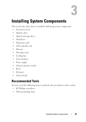
... system components: • Front drive bezel • Diskette drive • Optical and tape drives • Hard drives • Expansion cards • SAS controller card • Memory • Microprocessor • Cooling fans • System battery • Power supply • Chassis intrusion switch • Bezel • I/O panel • System board Recommended Tools You...
... system components: • Front drive bezel • Diskette drive • Optical and tape drives • Hard drives • Expansion cards • SAS controller card • Memory • Microprocessor • Cooling fans • System battery • Power supply • Chassis intrusion switch • Bezel • I/O panel • System board Recommended Tools You...


