Getting Started Guide
Page 5
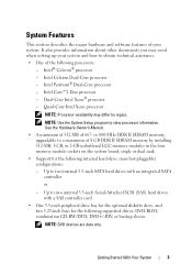
...-inch bays for the following internal hard-drive (non-hot-pluggable) configurations: - Intel Pentium® Dual-Core processor - single or dual rank. • Support for the following processors: - Getting Started With Your System 3 See the Hardware Owner's Manual. • A minimum of 512 MB...drives: DVD-ROM, combination CD-RW/DVD, DVD+/-RW, or backup device. Intel Core™2 Duo processor - Dual-Core Intel Xeon® processor - Intel® Celeron® processor - It also provides information about other documents you may differ by installing 512-MB, 1-GB, or ...
...-inch bays for the following internal hard-drive (non-hot-pluggable) configurations: - Intel Pentium® Dual-Core processor - single or dual rank. • Support for the following processors: - Getting Started With Your System 3 See the Hardware Owner's Manual. • A minimum of 512 MB...drives: DVD-ROM, combination CD-RW/DVD, DVD+/-RW, or backup device. Intel Core™2 Duo processor - Dual-Core Intel Xeon® processor - Intel® Celeron® processor - It also provides information about other documents you may differ by installing 512-MB, 1-GB, or ...

Getting Started Guide
Page 10
... system is installed before installing hardware or software not purchased with your system. Technical Specifications Processor Processor type Expansion Bus Bus type Expansion slots PCIe PCI Memory Architecture Memory module sockets • Intel® Celeron®...; processor • Intel Celeron Dual-Core processor • Intel Pentium® Dual-Core processor • Intel Core™2 Duo processor • Dual-Core Intel Xeon® processor • Quad-Core Intel Xeon processor NOTE: Processor availability may differ by region. PCI and...
... system is installed before installing hardware or software not purchased with your system. Technical Specifications Processor Processor type Expansion Bus Bus type Expansion slots PCIe PCI Memory Architecture Memory module sockets • Intel® Celeron®...; processor • Intel Celeron Dual-Core processor • Intel Pentium® Dual-Core processor • Intel Core™2 Duo processor • Dual-Core Intel Xeon® processor • Quad-Core Intel Xeon processor NOTE: Processor availability may differ by region. PCI and...
Hardware Owner's Manual
Page 5
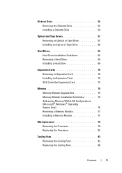
... Addressing Memory With 8-GB Configurations (Microsoft® Windows® Operating System Only 76 Removing a Memory Module 77 Installing a Memory Module 77 Microprocessor 79 Removing the Processor 79 Replacing the Processor 82 Cooling Fans 83 Removing the Cooling Fans 83 Replacing the Cooling Fans 86 Contents 5
... Addressing Memory With 8-GB Configurations (Microsoft® Windows® Operating System Only 76 Removing a Memory Module 77 Installing a Memory Module 77 Microprocessor 79 Removing the Processor 79 Replacing the Processor 82 Cooling Fans 83 Removing the Cooling Fans 83 Replacing the Cooling Fans 86 Contents 5
Hardware Owner's Manual
Page 16
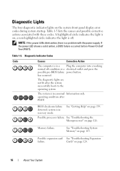
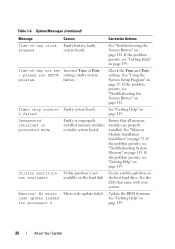
... diagnostic indicator lights on ; NOTE: If the power LEDs blink amber, there is on the system front panel display error codes during system startup. Possible processor failure. Table 1-5. Cards" on page 139. See "Getting Help" on page 124. 16 About Your System Memory failure. has occurred.
... diagnostic indicator lights on ; NOTE: If the power LEDs blink amber, there is on the system front panel display error codes during system startup. Possible processor failure. Table 1-5. Cards" on page 139. See "Getting Help" on page 124. 16 About Your System Memory failure. has occurred.
Hardware Owner's Manual
Page 26
... page 75. Ensure that came with your system. See "Memory Module Installation Guidelines" on the boot hard drive. Table 1-6. No micro code update loaded for processor 0 Micro code update failed.
... page 75. Ensure that came with your system. See "Memory Module Installation Guidelines" on the boot hard drive. Table 1-6. No micro code update loaded for processor 0 Micro code update failed.

Hardware Owner's Manual
Page 33
... Do Not Report to suppress all error messages relating to Disabled, the memory tests are conducted. Displays the amount of the processor. Memory Information Screen Table 2-3 lists the options and descriptions for host systems that have keyboards attached. When set to the system...frequency of main memory in the system. CPU Information Screen Option 64-bit Core Speed Bus Speed Description Specifies if the installed processor supports Intel® 64-bit extensions. Table 2-4. Memory Information Screen Option System Memory Size System Memory Type System Memory Speed ...
... Do Not Report to suppress all error messages relating to Disabled, the memory tests are conducted. Displays the amount of the processor. Memory Information Screen Table 2-3 lists the options and descriptions for host systems that have keyboards attached. When set to the system...frequency of main memory in the system. CPU Information Screen Option 64-bit Core Speed Bus Speed Description Specifies if the installed processor supports Intel® 64-bit extensions. Table 2-4. Memory Information Screen Option System Memory Size System Memory Type System Memory Speed ...

Hardware Owner's Manual
Page 34
... on the SATA Configuration screen. 34 Using the System Setup Program CPU Information Screen (continued) Option Description Logical Processor (Enabled default) Displays when the processor supports Hyper-Threading technology. Virtualization Technology Displays when the processor(s) support Virtualization (Disabled default) Technology. Hardware Prefetcher (Enabled default) Enables or disables the hardware prefetcher. SATA Configuration Screen...
... on the SATA Configuration screen. 34 Using the System Setup Program CPU Information Screen (continued) Option Description Logical Processor (Enabled default) Displays when the processor supports Hyper-Threading technology. Virtualization Technology Displays when the processor(s) support Virtualization (Disabled default) Technology. Hardware Prefetcher (Enabled default) Enables or disables the hardware prefetcher. SATA Configuration Screen...
Hardware Owner's Manual
Page 46
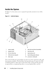
... 7 5.25-inch drive bays (2) 9 drive cage 4 2 heat sink and shroud assembly 4 hard drives (2) 6 tape backup unit 8 bezel sliding plate release 10 processor cooling fan The system board can accommodate one processor, four expansion cards, and four memory modules. The hard drive bays provide space for up to provide an interior view of...
... 7 5.25-inch drive bays (2) 9 drive cage 4 2 heat sink and shroud assembly 4 hard drives (2) 6 tape backup unit 8 bezel sliding plate release 10 processor cooling fan The system board can accommodate one processor, four expansion cards, and four memory modules. The hard drive bays provide space for up to provide an interior view of...

Hardware Owner's Manual
Page 79
...came with the system. See "Running the System Diagnostics" on page 30. See "System Setup Options" on page 130. Removing the Processor CAUTION: Only trained service technicians are operating properly. Before you begin this procedure, review the safety instructions that the new memory does not... and generates the following message: The amount of the components inside the system. See "Opening the System" on the system board. The processor and its associated internal cache memory are contained in a land grid array (LGA) package that is installed in their connectors, and repeat ...
...came with the system. See "Running the System Diagnostics" on page 30. See "System Setup Options" on page 130. Removing the Processor CAUTION: Only trained service technicians are operating properly. Before you begin this procedure, review the safety instructions that the new memory does not... and generates the following message: The amount of the components inside the system. See "Opening the System" on the system board. The processor and its associated internal cache memory are contained in a land grid array (LGA) package that is installed in their connectors, and repeat ...

Hardware Owner's Manual
Page 80
... attached peripherals, and disconnect the system from the fan housing on page 47. 3 Detach the diskette cable that they have had sufficient time to the processor cooling fan housing. See Figure 3-21. 5 Tilt the heat sink and shroud assembly away from the electrical outlet. 2 Open the system. See "Opening the System... pivot bracket and lift it aside. 4 Using a #2 Phillips screwdriver, loosen the two captive screws holding the heat sink and shroud assembly in place. CAUTION: The processor and heat sink can get very hot during normal operation.
... attached peripherals, and disconnect the system from the fan housing on page 47. 3 Detach the diskette cable that they have had sufficient time to the processor cooling fan housing. See Figure 3-21. 5 Tilt the heat sink and shroud assembly away from the electrical outlet. 2 Open the system. See "Opening the System... pivot bracket and lift it aside. 4 Using a #2 Phillips screwdriver, loosen the two captive screws holding the heat sink and shroud assembly in place. CAUTION: The processor and heat sink can get very hot during normal operation.

Hardware Owner's Manual
Page 81
... lever up so that the socket is ready for the new processor. Bending the pins can permanently damage the system board. See Figure 3-22. 7 Rotate the processor shield upward and out of the way. 8 Lift the processor out of the pins on the ZIF socket when removing the... processor. Figure 3-21. Installing and Removing the Heat Sink 1 2 3 1 heat sink and shroud assembly 3 captive screws...
... lever up so that the socket is ready for the new processor. Bending the pins can permanently damage the system board. See Figure 3-22. 7 Rotate the processor shield upward and out of the way. 8 Lift the processor out of the pins on the ZIF socket when removing the... processor. Figure 3-21. Installing and Removing the Heat Sink 1 2 3 1 heat sink and shroud assembly 3 captive screws...

Hardware Owner's Manual
Page 82
... bend the pins in the socket. Installing and Removing a Processor 2 3 1 4 6 5 1 notch in the socket. When the processor is not positioned all the way up, move it on the processor socket is positioned correctly, it engages easily into the socket....Installing System Components See Figure 3-22. 3 Install the processor in processor (2) 3 socket-release lever 5 processor shield 2 processor 4 ZIF socket 6 socket key (2) Replacing the Processor 1 Unpack the new processor. 2 Align the processor with the socket keys on the processor when handling the processor or the system board.
... bend the pins in the socket. Installing and Removing a Processor 2 3 1 4 6 5 1 notch in the socket. When the processor is not positioned all the way up, move it on the processor socket is positioned correctly, it engages easily into the socket....Installing System Components See Figure 3-22. 3 Install the processor in processor (2) 3 socket-release lever 5 processor shield 2 processor 4 ZIF socket 6 socket key (2) Replacing the Processor 1 Unpack the new processor. 2 Align the processor with the socket keys on the processor when handling the processor or the system board.

Hardware Owner's Manual
Page 83
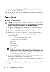
... Components 83 See "Closing the System" on page 47. 9 Reconnect the system to the top of the cooling fan assembly. See "Removing the Processor" on the system and attached peripherals. Each contains a shroud that came with the system board, then tighten them to secure the heat sink assembly ...disconnect the system from the bottom of the components inside the system. See "Opening the System" on page 47. d When the processor is part of the processor. 6 Place the heat sink assembly back onto the heat sink assembly bracket and tilt the heat sink assembly down until it snaps into...
... Components 83 See "Closing the System" on page 47. 9 Reconnect the system to the top of the cooling fan assembly. See "Removing the Processor" on the system and attached peripherals. Each contains a shroud that came with the system board, then tighten them to secure the heat sink assembly ...disconnect the system from the bottom of the components inside the system. See "Opening the System" on page 47. d When the processor is part of the processor. 6 Place the heat sink assembly back onto the heat sink assembly bracket and tilt the heat sink assembly down until it snaps into...

Hardware Owner's Manual
Page 84
...bracket mount. c Press the bottom release tab and shift it forward to the chassis (see Figure 3-24). c Lift the fan out. See "Removing the Processor" on page 79. NOTE: The SAS hard drive cooling fan is present only if a SAS 6i/R integrated controller card is installed. 4 If you are ...removing the larger processor cooling fan: a Remove the heat sink and shroud assembly. d Slide the fan toward the back panel and lift the fan out. 84 Installing System ...
...bracket mount. c Press the bottom release tab and shift it forward to the chassis (see Figure 3-24). c Lift the fan out. See "Removing the Processor" on page 79. NOTE: The SAS hard drive cooling fan is present only if a SAS 6i/R integrated controller card is installed. 4 If you are ...removing the larger processor cooling fan: a Remove the heat sink and shroud assembly. d Slide the fan toward the back panel and lift the fan out. 84 Installing System ...

Hardware Owner's Manual
Page 87
... 5 heat sink fan 2 cable slot 4 fan connector cable 6 front drive bezel 5 Replace the heat sink and shroud assembly (see "Removing the Processor" on page 79). If you are replacing the processor cooling fan: 1 Align the bottom mounting tabs on the replacement fan with the securing tabs on the chassis bracket mount. 2 Slide...
... 5 heat sink fan 2 cable slot 4 fan connector cable 6 front drive bezel 5 Replace the heat sink and shroud assembly (see "Removing the Processor" on page 79). If you are replacing the processor cooling fan: 1 Align the bottom mounting tabs on the replacement fan with the securing tabs on the chassis bracket mount. 2 Slide...
Hardware Owner's Manual
Page 90
... board and drives. Loosen the two captive screws holding the heat sink and shroud assembly in the system frame as you replace them to the processor cooling fan housing.
... board and drives. Loosen the two captive screws holding the heat sink and shroud assembly in the system frame as you replace them to the processor cooling fan housing.
Hardware Owner's Manual
Page 94
...technicians are authorized to the electrical outlet, and turn on page 47. 3 Remove the heat sink and shroud assembly. Do not remove the processor, however. 4 Remove the large processor cooling fan. See "Opening the System" on the system. Before you begin this procedure, review the safety instructions that came with the ...5 Reconnect the system to remove the system cover and access any of the system, then lift it outward. 94 Installing System Components See "Removing the Processor" on page 83. 5 Remove the two bezel release screws. See "Removing the Cooling Fans" on page 79.
...technicians are authorized to the electrical outlet, and turn on page 47. 3 Remove the heat sink and shroud assembly. Do not remove the processor, however. 4 Remove the large processor cooling fan. See "Opening the System" on the system. Before you begin this procedure, review the safety instructions that came with the ...5 Reconnect the system to remove the system cover and access any of the system, then lift it outward. 94 Installing System Components See "Removing the Processor" on page 83. 5 Remove the two bezel release screws. See "Removing the Cooling Fans" on page 79.
Hardware Owner's Manual
Page 95
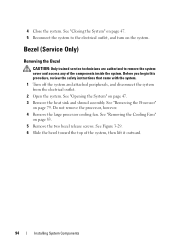
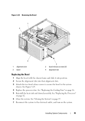
Installing System Components 95 See "Replacing the Processor" on page 86. 5 Reinstall the heat sink and shroud assembly. Removing the Bezel 1 4 3 1 alignment slot 3 bezel 2 2 bezel release screws (2) 4 alignment tab Replacing the Bezel 1 Align ... system chassis. See "Closing the System" on the system. See "Replacing the Cooling Fans" on page 82. 6 Close the system. See Figure 3-29. 4 Replace the processor fan. Figure 3-29.
Installing System Components 95 See "Replacing the Processor" on page 86. 5 Reinstall the heat sink and shroud assembly. Removing the Bezel 1 4 3 1 alignment slot 3 bezel 2 2 bezel release screws (2) 4 alignment tab Replacing the Bezel 1 Align ... system chassis. See "Closing the System" on the system. See "Replacing the Cooling Fans" on page 82. 6 Close the system. See Figure 3-29. 4 Replace the processor fan. Figure 3-29.

Hardware Owner's Manual
Page 96
...re-route cables correctly. 6 Disconnect the I /O panel assembly to remove the system cover and access any of the components inside the system. See "Removing the Processor" on page 47. 3 Remove the heat sink and shroud assembly. See "Removing the Cooling Fans" on page 94. NOTICE: Carefully note the routing of each... that you disconnect it, so that came with the system. I /O panel assembly out of the system. 96 Installing System Components Do not remove the processor, however. 4 Remove the processor cooling fan. See "Removing the Bezel" on page 83. 5 Remove the front bezel.
...re-route cables correctly. 6 Disconnect the I /O panel assembly to remove the system cover and access any of the components inside the system. See "Removing the Processor" on page 47. 3 Remove the heat sink and shroud assembly. See "Removing the Cooling Fans" on page 94. NOTICE: Carefully note the routing of each... that you disconnect it, so that came with the system. I /O panel assembly out of the system. 96 Installing System Components Do not remove the processor, however. 4 Remove the processor cooling fan. See "Removing the Bezel" on page 83. 5 Remove the front bezel.
Hardware Owner's Manual
Page 98
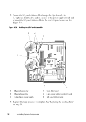
Figure 3-31. See Figure 3-31. 3 Secure the I/O panel ribbon cable through the clips beneath the 3.5 optional diskette drive and on the side of the power supply shroud, and connect the I/O panel ribbon cable to system board 6 I /O panel connector. Cabling the I/O Panel Assembly 5 6 1 4 1 I/O panel connector 3 I/O panel assembly 5 cable clip on page 86. 98 Installing System Components See "Replacing the Cooling Fans" on power supply 3 2 2 front drive bezel 4 4-pin power cable to the new I /O panel ribbon cable 4 Replace the large processor cooling fan.
Figure 3-31. See Figure 3-31. 3 Secure the I/O panel ribbon cable through the clips beneath the 3.5 optional diskette drive and on the side of the power supply shroud, and connect the I/O panel ribbon cable to system board 6 I /O panel connector. Cabling the I/O Panel Assembly 5 6 1 4 1 I/O panel connector 3 I/O panel assembly 5 cable clip on page 86. 98 Installing System Components See "Replacing the Cooling Fans" on power supply 3 2 2 front drive bezel 4 4-pin power cable to the new I /O panel ribbon cable 4 Replace the large processor cooling fan.


