
Getting Started Guide
Page 9
Getting Started With Your System 7 Adjust the monitor's controls until the displayed image is satisfactory. Turn on the System and Monitor Press the power button on the system and the monitor. Connect the System to Power Connect the system's power cable to the system. Next, plug the other end of the power cable into a grounded electrical outlet or a separate power source such as an uninterrupted power supply (UPS) or a power distribution unit (PDU). The power indicators should light.
Getting Started With Your System 7 Adjust the monitor's controls until the displayed image is satisfactory. Turn on the System and Monitor Press the power button on the system and the monitor. Connect the System to Power Connect the system's power cable to the system. Next, plug the other end of the power cable into a grounded electrical outlet or a separate power source such as an uninterrupted power supply (UPS) or a power distribution unit (PDU). The power indicators should light.

Getting Started Guide
Page 12
Connectors (continued) Front USB Internally accessible SATA channels USB key (for memory key) Video Video type Video memory Power AC power supply (per power supply) Wattage Voltage Heat dissipation CMOS Backup Battery Physical Height Width Depth Weight (maximum configuration) one 4-pin USB 2.0-compliant (CD/DVD/USB key) one 4-pin USB 2.0-...
Connectors (continued) Front USB Internally accessible SATA channels USB key (for memory key) Video Video type Video memory Power AC power supply (per power supply) Wattage Voltage Heat dissipation CMOS Backup Battery Physical Height Width Depth Weight (maximum configuration) one 4-pin USB 2.0-compliant (CD/DVD/USB key) one 4-pin USB 2.0-...
Hardware Owner's Manual
Page 3
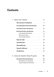
Contents 1 About Your System 9 Other Information You May Need 9 Accessing System Features During Startup 10 Front-Panel Features and Indicators 11 Back-Panel Features and Indicators 13 Connecting External Devices 14 NIC Indicator Codes 14 Power Supply Indicators 15 Diagnostic Lights 16 System Messages 18 Warning Messages 27 Diagnostics Messages 27 Alert Messages 27 2 Using the System Setup Program 29 Entering the System Setup Program 29 Responding to Error Messages 29 Using the System Setup Program 30 Contents 3
Contents 1 About Your System 9 Other Information You May Need 9 Accessing System Features During Startup 10 Front-Panel Features and Indicators 11 Back-Panel Features and Indicators 13 Connecting External Devices 14 NIC Indicator Codes 14 Power Supply Indicators 15 Diagnostic Lights 16 System Messages 18 Warning Messages 27 Diagnostics Messages 27 Alert Messages 27 2 Using the System Setup Program 29 Entering the System Setup Program 29 Responding to Error Messages 29 Using the System Setup Program 30 Contents 3
Hardware Owner's Manual
Page 6
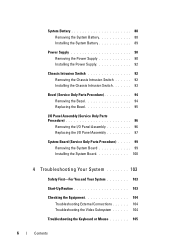
System Battery 88 Removing the System Battery 88 Installing the System Battery 89 Power Supply 90 Removing the Power Supply 90 Installing the Power Supply 92 Chassis Intrusion Switch 92 Removing the Chassis Intrusion Switch 92 Installing the Chassis Intrusion Switch 93 Bezel (Service Only Parts Procedure 94 Removing the ...
System Battery 88 Removing the System Battery 88 Installing the System Battery 89 Power Supply 90 Removing the Power Supply 90 Installing the Power Supply 92 Chassis Intrusion Switch 92 Removing the Chassis Intrusion Switch 92 Installing the Chassis Intrusion Switch 93 Bezel (Service Only Parts Procedure 94 Removing the ...
Hardware Owner's Manual
Page 7
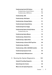
...Device 108 Troubleshooting a NIC 109 Troubleshooting a Wet System 111 Troubleshooting a Damaged System 111 Troubleshooting the System Battery 112 Troubleshooting Power Supply 113 Troubleshooting System Cooling Problems 114 Troubleshooting a Fan 114 Troubleshooting System Memory 115 Troubleshooting a Diskette Drive 117 Troubleshooting an ... . 123 Troubleshooting Expansion Cards 124 Troubleshooting the Microprocessor 126 5 Running the System Diagnostics 129 Using Dell PowerEdge Diagnostics 129 System Diagnostics Features 129 When to Use the System Diagnostics 130 Contents 7
...Device 108 Troubleshooting a NIC 109 Troubleshooting a Wet System 111 Troubleshooting a Damaged System 111 Troubleshooting the System Battery 112 Troubleshooting Power Supply 113 Troubleshooting System Cooling Problems 114 Troubleshooting a Fan 114 Troubleshooting System Memory 115 Troubleshooting a Diskette Drive 117 Troubleshooting an ... . 123 Troubleshooting Expansion Cards 124 Troubleshooting the Microprocessor 126 5 Running the System Diagnostics 129 Using Dell PowerEdge Diagnostics 129 System Diagnostics Features 129 When to Use the System Diagnostics 130 Contents 7

Hardware Owner's Manual
Page 12
...About Your System Front-Panel Components (continued) Item Component Icon 2 power button 3 power light 4 flex bay 5 lower 5.25-inch drive bay 6 upper 5.25-inch drive bay Description The power button controls the DC power supply output to the system. If the system is not running an ACPI...-compliant operating system, the system performs a graceful shutdown before Power-On Self Test (POST). The system is off . Blinking...
...About Your System Front-Panel Components (continued) Item Component Icon 2 power button 3 power light 4 flex bay 5 lower 5.25-inch drive bay 6 upper 5.25-inch drive bay Description The power button controls the DC power supply output to the system. If the system is not running an ACPI...-compliant operating system, the system performs a graceful shutdown before Power-On Self Test (POST). The system is off . Blinking...

Hardware Owner's Manual
Page 15
See "Using the System Setup Program" on page 29. 1000-Mbps connection 100-Mbps connection 10-Mbps connection Power Supply Indicators The voltage selection switch on page 29. NIC Indicator Codes Indicator Type Indicator Code Activity Off Blinking Link Off Yellow Orange ..."Technical Specifications" in the System Setup program. When off , the NIC is not connected to the network or the NIC is disabled in your power source is being sent or received. Voltage Selection Switch If your Getting Started Guide. Table 1-4. About Your System 15 Table 1-3. Ensure that the ...
See "Using the System Setup Program" on page 29. 1000-Mbps connection 100-Mbps connection 10-Mbps connection Power Supply Indicators The voltage selection switch on page 29. NIC Indicator Codes Indicator Type Indicator Code Activity Off Blinking Link Off Yellow Orange ..."Technical Specifications" in the System Setup program. When off , the NIC is not connected to the network or the NIC is disabled in your power source is being sent or received. Voltage Selection Switch If your Getting Started Guide. Table 1-4. About Your System 15 Table 1-3. Ensure that the ...
Hardware Owner's Manual
Page 16
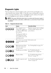
Table 1-5 lists the causes and possible corrective actions associated with the power supply. NOTE: If the power LEDs blink amber, there is in recovery mode. has occurred. BIOS checksum failure detected; See "Troubleshooting System Memory" on page 139. Possible .... a non-highlighted circle indicates the light is in a Plug the computer into a working normal off . If the power LED shows a solid amber, a BIOS failure occurred before Power-On Self Test (POST). operating condition after the system successfully boots to the operating system. See "Getting Help" on page 115. Memory ...
Table 1-5 lists the causes and possible corrective actions associated with the power supply. NOTE: If the power LEDs blink amber, there is in recovery mode. has occurred. BIOS checksum failure detected; See "Troubleshooting System Memory" on page 139. Possible .... a non-highlighted circle indicates the light is in a Plug the computer into a working normal off . If the power LED shows a solid amber, a BIOS failure occurred before Power-On Self Test (POST). operating condition after the system successfully boots to the operating system. See "Getting Help" on page 115. Memory ...
Hardware Owner's Manual
Page 45
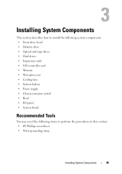
...; Optical and tape drives • Hard drives • Expansion cards • SAS controller card • Memory • Microprocessor • Cooling fans • System battery • Power supply • Chassis intrusion switch • Bezel • I/O panel • System board Recommended Tools You may need the following items to perform the procedures in this...
...; Optical and tape drives • Hard drives • Expansion cards • SAS controller card • Memory • Microprocessor • Cooling fans • System battery • Power supply • Chassis intrusion switch • Bezel • I/O panel • System board Recommended Tools You may need the following items to perform the procedures in this...
Hardware Owner's Manual
Page 46
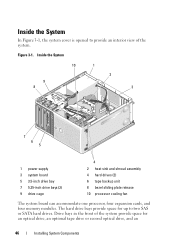
... front of the system. Inside the System In Figure 3-1, the system cover is opened to two SAS or SATA hard drives. Inside the System 10 1 9 8 2 3 7 6 5 1 power supply 3 system board 5 3.5-inch drive bay 7 5.25-inch drive bays (2) 9 drive cage 4 2 heat sink and shroud assembly 4 hard drives (2) 6 tape backup unit 8 bezel sliding plate release...
... front of the system. Inside the System In Figure 3-1, the system cover is opened to two SAS or SATA hard drives. Inside the System 10 1 9 8 2 3 7 6 5 1 power supply 3 system board 5 3.5-inch drive bay 7 5.25-inch drive bays (2) 9 drive cage 4 2 heat sink and shroud assembly 4 hard drives (2) 6 tape backup unit 8 bezel sliding plate release...
Hardware Owner's Manual
Page 47
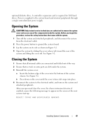
Power is required for SAS hard drives. See Figure 3-2. Closing the System 1 Ensure that all internal cables are connected and folded out of the way. 2 Ensure ... off the system and attached peripherals, and disconnect the system from the electrical outlet. 2 Press the power button to the system board and internal peripherals through a single nonredundant power supply. optional diskette drive. A controller expansion card is supplied to ground the system board. 3 Lay the system on the system and attached peripherals. Before you...
Power is required for SAS hard drives. See Figure 3-2. Closing the System 1 Ensure that all internal cables are connected and folded out of the way. 2 Ensure ... off the system and attached peripherals, and disconnect the system from the electrical outlet. 2 Press the power button to the system board and internal peripherals through a single nonredundant power supply. optional diskette drive. A controller expansion card is supplied to ground the system board. 3 Lay the system on the system and attached peripherals. Before you...
Hardware Owner's Manual
Page 90
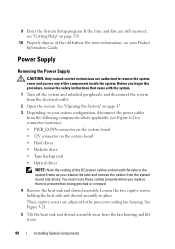
... place. See Figure 3-21. 5 Tilt the heat sink and shroud assembly away from the system board and drives. Power Supply Removing the Power Supply CAUTION: Only trained service technicians are authorized to prevent their being pinched or crimped. 4 Remove the heat sink and ...Turn off the system and attached peripherals, and disconnect the system from the following components where applicable (see your system configuration, disconnect the power cables from the electrical outlet. 2 Open the system. For more information, see Figure 6-2 for connector locations): • PWR_CONN connector ...
... place. See Figure 3-21. 5 Tilt the heat sink and shroud assembly away from the system board and drives. Power Supply Removing the Power Supply CAUTION: Only trained service technicians are authorized to prevent their being pinched or crimped. 4 Remove the heat sink and ...Turn off the system and attached peripherals, and disconnect the system from the following components where applicable (see your system configuration, disconnect the power cables from the electrical outlet. 2 Open the system. For more information, see Figure 6-2 for connector locations): • PWR_CONN connector ...

Hardware Owner's Manual
Page 91
...I/O panel and SATA cables (if present) attached to the routing clips on the side of the power supply. 7 Using a #2 Phillips screwdriver, remove the four Phillips screws that secure the power supply to the new power supply. See Figure 3-27. 9 Remove the cable clip and set it aside to attach to the back... panel. 8 Press the power-supply release tab down and slide the power supply toward the front of the system, then lift ...
...I/O panel and SATA cables (if present) attached to the routing clips on the side of the power supply. 7 Using a #2 Phillips screwdriver, remove the four Phillips screws that secure the power supply to the new power supply. See Figure 3-27. 9 Remove the cable clip and set it aside to attach to the back... panel. 8 Press the power-supply release tab down and slide the power supply toward the front of the system, then lift ...

Hardware Owner's Manual
Page 92
... inside the system. Installing the Power Supply 1 Attach the cable clip to the new power supply. 2 Align the power supply mounting holes with the mounting holes on the back panel. 3 Slide the power supply toward the back panel until it snaps into place over the power-supply release tab. 4 Using a ...Switch CAUTION: Only trained service technicians are authorized to remove the system cover and access any of the power supply. 6 Depending on your system configuration, connect the following power cables: • PWR_CONN connector on the system board • 12V connector on the system board ...
... inside the system. Installing the Power Supply 1 Attach the cable clip to the new power supply. 2 Align the power supply mounting holes with the mounting holes on the back panel. 3 Slide the power supply toward the back panel until it snaps into place over the power-supply release tab. 4 Using a ...Switch CAUTION: Only trained service technicians are authorized to remove the system cover and access any of the power supply. 6 Depending on your system configuration, connect the following power cables: • PWR_CONN connector on the system board • 12V connector on the system board ...
Hardware Owner's Manual
Page 98
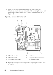
Figure 3-31. See "Replacing the Cooling Fans" on power supply 3 2 2 front drive bezel 4 4-pin power cable to the new I/O panel connector. 3 Secure the I/O panel ribbon cable through the clips beneath the 3.5 optional diskette drive and on the side of the power supply shroud, and connect the I/O panel ribbon cable to system board 6 I/O panel ribbon cable 4 Replace the large processor cooling fan. See Figure 3-31. Cabling the I/O Panel Assembly 5 6 1 4 1 I/O panel connector 3 I/O panel assembly 5 cable clip on page 86. 98 Installing System Components
Figure 3-31. See "Replacing the Cooling Fans" on power supply 3 2 2 front drive bezel 4 4-pin power cable to the new I/O panel connector. 3 Secure the I/O panel ribbon cable through the clips beneath the 3.5 optional diskette drive and on the side of the power supply shroud, and connect the I/O panel ribbon cable to system board 6 I/O panel ribbon cable 4 Replace the large processor cooling fan. See Figure 3-31. Cabling the I/O Panel Assembly 5 6 1 4 1 I/O panel connector 3 I/O panel assembly 5 cable clip on page 86. 98 Installing System Components
Hardware Owner's Manual
Page 99
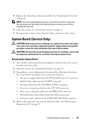
... Only) CAUTION: Only trained service technicians are authorized to cool before installing the heat sink. 6 Close the system. See Figure 6-2 for connector locations. • Two power-supply cables from the PWR_CONN and 12V connectors • Diskette data cable from the FLOPPY connector • I/O panel cable from the CONTROL_PANEL connector • Processor cooling...
... Only) CAUTION: Only trained service technicians are authorized to cool before installing the heat sink. 6 Close the system. See Figure 6-2 for connector locations. • Two power-supply cables from the PWR_CONN and 12V connectors • Diskette data cable from the FLOPPY connector • I/O panel cable from the CONTROL_PANEL connector • Processor cooling...

Hardware Owner's Manual
Page 101
... page 47. 9 Reconnect the system to the SATA connector(s) • Intrusion switch cable from the INTRUSION SWITCH connector 8 Close the system. See Figure 6-2. • Two power-supply cables to the PWR_CONN and 12V connectors • If applicable, diskette data cable to the FLOPPY connector • I/O panel cable to the CONTROL_PANEL connector •...
... page 47. 9 Reconnect the system to the SATA connector(s) • Intrusion switch cable from the INTRUSION SWITCH connector 8 Close the system. See Figure 6-2. • Two power-supply cables to the PWR_CONN and 12V connectors • If applicable, diskette data cable to the FLOPPY connector • I/O panel cable to the CONTROL_PANEL connector •...
Hardware Owner's Manual
Page 112
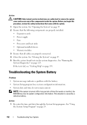
... the System Diagnostics" on page 139. See "Opening the System" on page 47. 2 Ensure that the following components are properly installed: • Expansion cards • Power supply • Fans • Processors and heat sinks • Optional installed drivers • Memory modules 3 Ensure that came with the battery. • System Setup program loses...
... the System Diagnostics" on page 139. See "Opening the System" on page 47. 2 Ensure that the following components are properly installed: • Expansion cards • Power supply • Fans • Processors and heat sinks • Optional installed drivers • Memory modules 3 Ensure that came with the battery. • System Setup program loses...

Hardware Owner's Manual
Page 113
... see "Getting Help" on page 47. 4 Locate the faulty power supply. See "Opening the System" on page 139. If the problem is not resolved by a defective battery. Troubleshooting Power Supply Problem • Power-supply fault indicator is lit. NOTICE: Setting the voltage selection switch to...operate normally except for the time kept in the System Setup program, replace the battery. The power supply's fault indicator is blinking amber. Troubleshooting Your System 113 See "Power Supply Indicators" on the system. 4 Enter the System Setup program. If the system seems to ...
... see "Getting Help" on page 47. 4 Locate the faulty power supply. See "Opening the System" on page 139. If the problem is not resolved by a defective battery. Troubleshooting Power Supply Problem • Power-supply fault indicator is lit. NOTICE: Setting the voltage selection switch to...operate normally except for the time kept in the System Setup program, replace the battery. The power supply's fault indicator is blinking amber. Troubleshooting Your System 113 See "Power Supply Indicators" on the system. 4 Enter the System Setup program. If the system seems to ...
Hardware Owner's Manual
Page 114
.... Troubleshooting a Fan Problem • System-status indicator is removed or has failed. See "Removing the Power Supply" on page 47. NOTE: After installing a power supply, allow several seconds for the system to recognize the power supply and to signify that the power supply is properly installed by removing and reinstalling it is working properly. If the problem persists...
.... Troubleshooting a Fan Problem • System-status indicator is removed or has failed. See "Removing the Power Supply" on page 47. NOTE: After installing a power supply, allow several seconds for the system to recognize the power supply and to signify that the power supply is properly installed by removing and reinstalling it is working properly. If the problem persists...


