Operating Guide
Page 2
... one described in the operating instructions and adhere to the presence of any kind into the set may touch dangerous voltage points or short out parts that may cause hazards. 2 Never spill liquid of uninsulated "dangerous voltage" within the product's enclosure that could result in . This symbol is intended to alert...
... one described in the operating instructions and adhere to the presence of any kind into the set may touch dangerous voltage points or short out parts that may cause hazards. 2 Never spill liquid of uninsulated "dangerous voltage" within the product's enclosure that could result in . This symbol is intended to alert...

Operating Guide
Page 3
...covered. - Servicing Do not attempt to service the set near or over a radiator or heat register, or where it . Replacement parts When replacement parts are specified in damage and will prevent damage to the set from overheating, these slots and openings must never be walked on an unstable.... When the set . - Power-Cord Protection Route the power cord so that are required, be sure the service technician has used replacement parts specified by a qualified technician to restore the set , ask the service technician to perform routine safety checks (as opening or removing covers may...
...covered. - Servicing Do not attempt to service the set near or over a radiator or heat register, or where it . Replacement parts When replacement parts are specified in damage and will prevent damage to the set from overheating, these slots and openings must never be walked on an unstable.... When the set . - Power-Cord Protection Route the power cord so that are required, be sure the service technician has used replacement parts specified by a qualified technician to restore the set , ask the service technician to perform routine safety checks (as opening or removing covers may...
Operating Guide
Page 4
...this manual could void your used with the instructions, may result. Owner's Record The model and serial numbers are recyclable. DCR-HC62 Serial No. If you may not cause harmful interference, and (2) this product. Note This equipment has been tested and found...CA 92127 U.S.A. ACSerial No. 4 For customers in the U.S.A. Telephone number: 858-942-2230 This device complies with Part 15 of Conformity Trade Name: SONY Model No.: DCR-HC62 Responsible Party: Sony Electronics Inc. The number below . Read this first Before operating the unit, please read this equipment. Notes...
...this manual could void your used with the instructions, may result. Owner's Record The model and serial numbers are recyclable. DCR-HC62 Serial No. If you may not cause harmful interference, and (2) this product. Note This equipment has been tested and found...CA 92127 U.S.A. ACSerial No. 4 For customers in the U.S.A. Telephone number: 858-942-2230 This device complies with Part 15 of Conformity Trade Name: SONY Model No.: DCR-HC62 Responsible Party: Sony Electronics Inc. The number below . Read this first Before operating the unit, please read this equipment. Notes...

Operating Guide
Page 5
... between the equipment and receiver. - Consult the dealer or an experienced radio/TV technician for a digital device pursuant to Subpart B of Part 15 of cassette you can use in order to comply with "Memory Stick" compatible equipment Be sure to correct the interference by turning the...using a "Memory Stick Duo" with the limits for help. Reorient or relocate the receiving antenna. - "First Step Guide" for connecting the camcorder to radio or television reception, which the receiver is encouraged to try to insert the "Memory Stick Duo" into an outlet on the supplied CD...
... between the equipment and receiver. - Consult the dealer or an experienced radio/TV technician for a digital device pursuant to Subpart B of Part 15 of cassette you can use in order to comply with "Memory Stick" compatible equipment Be sure to correct the interference by turning the...using a "Memory Stick Duo" with the limits for help. Reorient or relocate the receiving antenna. - "First Step Guide" for connecting the camcorder to radio or television reception, which the receiver is encouraged to try to insert the "Memory Stick Duo" into an outlet on the supplied CD...
Operating Guide
Page 6
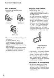
.... About changing the language setting • The on the LCD screen and the viewfinder. LCD panel • The camcorder is not available under the current recording or playback conditions. • The LCD screen and the viewfinder are manufactured using your...use and care" (p. 83). • When connecting your camcorder if necessary (p. 16). 6 Doing so might cause your camcorder. Take pictures of your camcorder to malfunction. Read this first (Continued) Using the camcorder • Do not hold the camcorder by the following parts. However, there may cause malfunctions. • Do not ...
.... About changing the language setting • The on the LCD screen and the viewfinder. LCD panel • The camcorder is not available under the current recording or playback conditions. • The LCD screen and the viewfinder are manufactured using your...use and care" (p. 83). • When connecting your camcorder if necessary (p. 16). 6 Doing so might cause your camcorder. Take pictures of your camcorder to malfunction. Read this first (Continued) Using the camcorder • Do not hold the camcorder by the following parts. However, there may cause malfunctions. • Do not ...
Operating Guide
Page 10
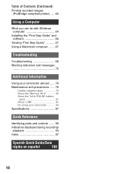
...First Step Guide 67 Using a Macintosh computer ........ 67 Troubleshooting Troubleshooting 68 Warning indicators and messages 75 Additional Information Using your camcorder abroad ...... 78 Maintenance and precautions ...... 79 Usable cassette tapes 79 About the "Memory Stick 80 About the "InfoLITHIUM" battery... pack 81 About i.LINK 82 On using your camcorder 83 Specifications 87 Quick Reference Identifying parts and controls ....... 90 Indicators displayed during recording/ playback 94 Index 97 Spanish Quick Guide/Guía ...
...First Step Guide 67 Using a Macintosh computer ........ 67 Troubleshooting Troubleshooting 68 Warning indicators and messages 75 Additional Information Using your camcorder abroad ...... 78 Maintenance and precautions ...... 79 Usable cassette tapes 79 About the "Memory Stick 80 About the "InfoLITHIUM" battery... pack 81 About i.LINK 82 On using your camcorder 83 Specifications 87 Quick Reference Identifying parts and controls ....... 90 Indicators displayed during recording/ playback 94 Index 97 Spanish Quick Guide/Guía ...
Operating Guide
Page 86
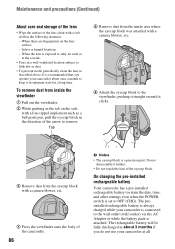
It is a precision part. Tab 5 Remove dust from the inside the viewfinder 1 Pull out the ...other settings even when the POWER switch is attached. The preinstalled rechargeable battery is always charged while your camcorder is connected to the wall outlet (wall socket) via the AC Adaptor or while the battery pack...ball point pen, pull the eyecup block in the following instances: - On charging the pre-installed rechargeable battery Your camcorder has a pre-installed rechargeable battery to remove. The rechargeable battery will be fully discharged in optimum state for a ...
It is a precision part. Tab 5 Remove dust from the inside the viewfinder 1 Pull out the ...other settings even when the POWER switch is attached. The preinstalled rechargeable battery is always charged while your camcorder is connected to the wall outlet (wall socket) via the AC Adaptor or while the battery pack...ball point pen, pull the eyecup block in the following instances: - On charging the pre-installed rechargeable battery Your camcorder has a pre-installed rechargeable battery to remove. The rechargeable battery will be fully discharged in optimum state for a ...
Operating Guide
Page 88
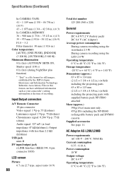
... 85 × 114 mm (2 1/2 × 3 3/8 × 4 1/2 in.) (w/h/d) including the projecting parts 63 × 85 × 115 mm (2 1/2 × 3 3/8 × 4 5/8 in.) (w/h/d) including the projecting parts with supplied battery pack NP-FH40 attached Mass (approx.) 390g(13oz) main unit only, 455g(1lb) including the ...16 ~ 38 1/2 in.) (16:9) F1.8 ~ 3.2 Filter diameter: 30 mm (1 3/16 in this format can have additional information such as your camcorder's setting information at load impedance 47 kΩ (kilohms)), Output impedance with less than 2.2 kΩ (kilohms) USB jack mini-B DV input/output jack...
... 85 × 114 mm (2 1/2 × 3 3/8 × 4 1/2 in.) (w/h/d) including the projecting parts 63 × 85 × 115 mm (2 1/2 × 3 3/8 × 4 5/8 in.) (w/h/d) including the projecting parts with supplied battery pack NP-FH40 attached Mass (approx.) 390g(13oz) main unit only, 455g(1lb) including the ...16 ~ 38 1/2 in.) (16:9) F1.8 ~ 3.2 Filter diameter: 30 mm (1 3/16 in this format can have additional information such as your camcorder's setting information at load impedance 47 kΩ (kilohms)), Output impedance with less than 2.2 kΩ (kilohms) USB jack mini-B DV input/output jack...

Operating Guide
Page 89
...; 81 mm (1 15/16 × 1 3/16 × 3 1/4 in.) (w/h/d) excluding the projecting parts Mass (approx.) 170 g (6.0 oz) excluding the power cord (mains lead) * See the label on the AC Adaptor for other countries. On trademarks • "Handycam" and are registered trademarks of Sony Corporation. • "Memory Stick," " ," "Memory Stick Duo," " ," "Memory Stick PRO Duo...
...; 81 mm (1 15/16 × 1 3/16 × 3 1/4 in.) (w/h/d) excluding the projecting parts Mass (approx.) 170 g (6.0 oz) excluding the power cord (mains lead) * See the label on the AC Adaptor for other countries. On trademarks • "Handycam" and are registered trademarks of Sony Corporation. • "Memory Stick," " ," "Memory Stick Duo," " ," "Memory Stick PRO Duo...
Operating Guide
Page 90
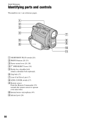
A NIGHTSHOT PLUS switch (24) B PHOTO button (20, 23) C Power zoom lever (24, 28) D OPEN/EJECT lever (18) E Hooks for a shoulder belt Attach a shoulder belt (optional). F Grip belt (17) G Lens (Carl Zeiss Lens) (7) H LENS COVER switch (17) I Remote sensor Point the Remote Commander (93) towards the remote sensor to operate your camcorder. J Internal stereo microphone (49) K Infrared port (24) 90 Quick Reference Identifying parts and controls The numbers in ( ) are reference pages.
A NIGHTSHOT PLUS switch (24) B PHOTO button (20, 23) C Power zoom lever (24, 28) D OPEN/EJECT lever (18) E Hooks for a shoulder belt Attach a shoulder belt (optional). F Grip belt (17) G Lens (Carl Zeiss Lens) (7) H LENS COVER switch (17) I Remote sensor Point the Remote Commander (93) towards the remote sensor to operate your camcorder. J Internal stereo microphone (49) K Infrared port (24) 90 Quick Reference Identifying parts and controls The numbers in ( ) are reference pages.
Operating Guide
Page 92
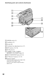
Identifying parts and controls (Continued) A POWER switch (15) B Viewfinder (17) C Eyecup (86) D Viewfinder lens adjustment lever (17) E DV interface (56, 58) F DC IN jack (12) G CAMERA-TAPE, CAMERA- MEMORY, PLAY/EDIT lamp (15) H REC START/STOP button (20, 22) I A/V Remote Connector (32, 56) J Tripod receptacle Attach the tripod (optional: the length of the screw must be less than 5.5 mm (7/32 in.)) to the tripod receptacle using a tripod screw. 92
Identifying parts and controls (Continued) A POWER switch (15) B Viewfinder (17) C Eyecup (86) D Viewfinder lens adjustment lever (17) E DV interface (56, 58) F DC IN jack (12) G CAMERA-TAPE, CAMERA- MEMORY, PLAY/EDIT lamp (15) H REC START/STOP button (20, 22) I A/V Remote Connector (32, 56) J Tripod receptacle Attach the tripod (optional: the length of the screw must be less than 5.5 mm (7/32 in.)) to the tripod receptacle using a tripod screw. 92


