
Owner's Manual
Page 1
...://www.pioneerelectronics.ca (Canada) Operating Instructions Mode d'emploi Manual de instrucciones AUDIO/VIDEO MULTI-CHANNEL RECEIVER RECEPTEUR AUDIOVISUEL A VOIES MULTIPLES RECEPTOR MULTICANAL DE AUDIO/VÍDEO VSX-820 Register your product on http://www.pioneerelectronics.com (US) http://www.pioneerelectronics.ca (Canada) ...loss or theft. • Receive free tips, updates and service bulletins on your new product • Improve product development Your input helps us continue to design products that meet your needs. • Receive a free Pioneer newsletter Registered customers can opt ...
...://www.pioneerelectronics.ca (Canada) Operating Instructions Mode d'emploi Manual de instrucciones AUDIO/VIDEO MULTI-CHANNEL RECEIVER RECEPTEUR AUDIOVISUEL A VOIES MULTIPLES RECEPTOR MULTICANAL DE AUDIO/VÍDEO VSX-820 Register your product on http://www.pioneerelectronics.com (US) http://www.pioneerelectronics.ca (Canada) ...loss or theft. • Receive free tips, updates and service bulletins on your new product • Improve product development Your input helps us continue to design products that meet your needs. • Receive a free Pioneer newsletter Registered customers can opt ...
Owner's Manual
Page 2
...digital device, pursuant to cause cancer and birth defect or other reproductive harm. Product Name: AUDIO/VIDEO MULTI-CHANNEL RECEIVER Model Number: VSX-820 Responsible Party Name: PIONEER ELECTRONICS (USA) INC. RECORD THESE NUMBERS ON YOUR ENCLOSED WARRANTY CARD AND KEEP IN A SAFE PLACE FOR FUTURE ...is properly disposed of the available power supply differs according to the following section carefully. Increase the separation between the equipment and receiver. - WARNING This equipment is for general household purposes. The voltage of after handling. D36-AP9-1_A1_En This Class B ...
...digital device, pursuant to cause cancer and birth defect or other reproductive harm. Product Name: AUDIO/VIDEO MULTI-CHANNEL RECEIVER Model Number: VSX-820 Responsible Party Name: PIONEER ELECTRONICS (USA) INC. RECORD THESE NUMBERS ON YOUR ENCLOSED WARRANTY CARD AND KEEP IN A SAFE PLACE FOR FUTURE ...is properly disposed of the available power supply differs according to the following section carefully. Increase the separation between the equipment and receiver. - WARNING This equipment is for general household purposes. The voltage of after handling. D36-AP9-1_A1_En This Class B ...
Owner's Manual
Page 4
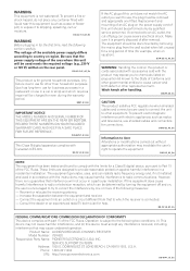
... the Advanced surround effects . . . . . 34 Listening in a safe place for buying this Pioneer product. After you start Checking what's in the box 7 Loading the batteries 7 Installing the receiver 7 Ventilation 8 04 Basic Setup Automatically setting up for surround sound (MCACC 29 Other problems when using...Connecting a TV and playback components . . . 23 Connecting using Phase Control 36 Listening with no HDMI terminal 24 Connecting a satellite receiver or other digital set-top box 25 Connecting an HDD/DVD recorder, VCR and other video sources 25 Using the component video jacks ...
... the Advanced surround effects . . . . . 34 Listening in a safe place for buying this Pioneer product. After you start Checking what's in the box 7 Loading the batteries 7 Installing the receiver 7 Ventilation 8 04 Basic Setup Automatically setting up for surround sound (MCACC 29 Other problems when using...Connecting a TV and playback components . . . 23 Connecting using Phase Control 36 Listening with no HDMI terminal 24 Connecting a satellite receiver or other digital set-top box 25 Connecting an HDD/DVD recorder, VCR and other video sources 25 Using the component video jacks ...

Owner's Manual
Page 5
...929; 7,392,195; 7,272,567 & other components 54 Preset Code List 55 10 Other connections Connecting an iPod 58 Connecting your iPod to the receiver . . . . . 58 iPod playback 59 Watching photos and video content 60 About iPod 60 Connecting a USB device 61 Connecting your USB device to the... receiver 61 Basic playback controls 61 Compressed audio compatibility 62 Bluetooth® ADAPTER for Wireless Enjoyment of Music 63 Wireless music play 63 Connecting...
...929; 7,392,195; 7,272,567 & other components 54 Preset Code List 55 10 Other connections Connecting an iPod 58 Connecting your iPod to the receiver . . . . . 58 iPod playback 59 Watching photos and video content 60 About iPod 60 Connecting a USB device 61 Connecting your USB device to the... receiver 61 Basic playback controls 61 Compressed audio compatibility 62 Bluetooth® ADAPTER for Wireless Enjoyment of Music 63 Wireless music play 63 Connecting...
Owner's Manual
Page 6
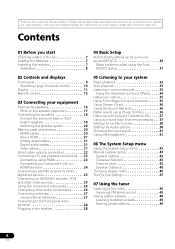
... speaker. 3 Connecting the components For surround sound, you'll want to hook up using a digital connection from the BD/DVD player to the receiver. • About video outputs connection (page 22) • Connecting a TV and playback components (page 23) • Connecting antennas (page 27) •...(page 29) 7 Basic playback (page 32) 8 Adjusting the sound as necessary 1 Before you start • Checking what's in the receiver (page 28) 4 Power On Make sure you've set the video input on your system • Automatically setting up for the best ...
... speaker. 3 Connecting the components For surround sound, you'll want to hook up using a digital connection from the BD/DVD player to the receiver. • About video outputs connection (page 22) • Connecting a TV and playback components (page 23) • Connecting antennas (page 27) •...(page 29) 7 Basic playback (page 32) 8 Adjusting the sound as necessary 1 Before you start • Checking what's in the receiver (page 28) 4 Power On Make sure you've set the video input on your system • Automatically setting up for the best ...
Owner's Manual
Page 7
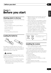
... hot or cold areas - Don't install it on the following places: - This may distort) - they may have different voltages. Installing the receiver • When installing this unit, make sure to put it on a level and stable surface. English Deutsch Français Italiano Nederlands Españ...ais Italiano Nederlands Español Before you start 01 Chapter 1: Before you start Checking what's in the box Please check that you've received the following supplied accessories: • Setup microphone • Remote control • Dry cell batteries (AAA size IEC R03) x2 •...
... hot or cold areas - Don't install it on the following places: - This may distort) - they may have different voltages. Installing the receiver • When installing this unit, make sure to put it on a level and stable surface. English Deutsch Français Italiano Nederlands Españ...ais Italiano Nederlands Español Before you start 01 Chapter 1: Before you start Checking what's in the box Please check that you've received the following supplied accessories: • Setup microphone • Remote control • Dry cell batteries (AAA size IEC R03) x2 •...

Owner's Manual
Page 8
... the equipment on top of the unit, make sure to leave space around the unit for ventilation and to improve heat dispersal (at the top). Receiver 40 cm (16 inches) Slot and openings in .) at least 40 cm (16 in the cabinet are never blocked or covered with performance and/or...
... the equipment on top of the unit, make sure to leave space around the unit for ventilation and to improve heat dispersal (at the top). Receiver 40 cm (16 inches) Slot and openings in .) at least 40 cm (16 in the cabinet are never blocked or covered with performance and/or...
Owner's Manual
Page 9
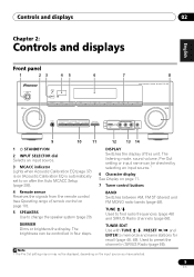
... checked by selecting an input source.1 6 Character display See Display on page 11. 7 Tuner control buttons 4 Remote sensor Receives the signals from the remote control (see Operating range of this unit. CHANNEL RECEIVER VSX-820 TUNE TUNER EDIT PRESET ENTER MASTER VOLUME PHONES AUTO/DIRECT LISTENING MODE STEREO/ALC STANDARD ADV SURROUND iPod iPhone...
... checked by selecting an input source.1 6 Character display See Display on page 11. 7 Tuner control buttons 4 Remote sensor Receives the signals from the remote control (see Operating range of this unit. CHANNEL RECEIVER VSX-820 TUNE TUNER EDIT PRESET ENTER MASTER VOLUME PHONES AUTO/DIRECT LISTENING MODE STEREO/ALC STANDARD ADV SURROUND iPod iPhone...
Owner's Manual
Page 10
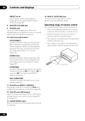
... sensor. • Direct sunlight or fluorescent light is shining onto the remote sensor. • The receiver is located near a device that is emitting infrared rays. • The receiver is no sound output from the speakers (page 41). 10 Listening mode buttons AUTO/DIRECT Switches between Auto surround mode (... Advance modes (page 35). When the headphones are obstacles between the various surround modes (page 34). 11 iPod iPhone DIRECT CONTROL Change the receiver's input to the iPod and enable iPod operations on the iPod (page 60). 12 iPod iPhone/USB terminal Use to connect your Apple iPod...
... sensor. • Direct sunlight or fluorescent light is shining onto the remote sensor. • The receiver is located near a device that is emitting infrared rays. • The receiver is no sound output from the speakers (page 41). 10 Listening mode buttons AUTO/DIRECT Switches between Auto surround mode (... Advance modes (page 35). When the headphones are obstacles between the various surround modes (page 34). 11 iPod iPhone DIRECT CONTROL Change the receiver's input to the iPod and enable iPod operations on the iPod (page 60). 12 iPod iPhone/USB terminal Use to connect your Apple iPod...
Owner's Manual
Page 11
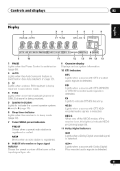
...signals is detected. MEM Blinks when a radio station is registered. 8 PRESET information or input signal indicator Shows the preset number of the receiver is on page 33). 3 ST Lights when a stereo FM broadcast is being received in auto stereo mode. 4 TUNE Lights when a normal broadcast channel or SIRIUS channel is being... indicators Lights to indicate the current speaker system, A and/or B (page 20). 6 Sleep timer indicator Lights when the receiver is in sleep mode (page 13). 7 Tuner/SIRIUS preset indicators PRESET Shows when a preset radio station is registered or called. NEO:6 When one of...
...signals is detected. MEM Blinks when a radio station is registered. 8 PRESET information or input signal indicator Shows the preset number of the receiver is on page 33). 3 ST Lights when a stereo FM broadcast is being received in auto stereo mode. 4 TUNE Lights when a normal broadcast channel or SIRIUS channel is being... indicators Lights to indicate the current speaker system, A and/or B (page 20). 6 Sleep timer indicator Lights when the receiver is in sleep mode (page 13). 7 Tuner/SIRIUS preset indicators PRESET Shows when a preset radio station is registered or called. NEO:6 When one of...

Owner's Manual
Page 13
...CH SELECT EQ 4 5 6 CH MIDNIGHT SPEAKERS 7 8 DIMMER CLR 0 / +10 D.ACCESS LEV 9 LEV ENTER PHASE CH SHIFT 14 15 16 17 RECEIVER 1 SLEEP Press to switch between standby and on page 33) and Stream Direct playback. Stream Direct playback bypasses the tone controls for Standard decoding and... STEREO/ BD MENU 7 DIRECT A.L.C. You can check the remaining sleep time at any time by pressing SLEEP once. 2 RECEIVER Switches the receiver between 2 Pro Logic II options (page 33). Switches between the various surround modes (page 34). STANDARD Press for the most accurate ...
...CH SELECT EQ 4 5 6 CH MIDNIGHT SPEAKERS 7 8 DIMMER CLR 0 / +10 D.ACCESS LEV 9 LEV ENTER PHASE CH SHIFT 14 15 16 17 RECEIVER 1 SLEEP Press to switch between standby and on page 33) and Stream Direct playback. Stream Direct playback bypasses the tone controls for Standard decoding and... STEREO/ BD MENU 7 DIRECT A.L.C. You can check the remaining sleep time at any time by pressing SLEEP once. 2 RECEIVER Switches the receiver between 2 Pro Logic II options (page 33). Switches between the various surround modes (page 34). STANDARD Press for the most accurate ...
Owner's Manual
Page 14
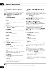
RETURN Confirm and exit the current menu screen. Press TUNER or SIRIUS first to access: TUNER EDIT Memorizes stations for Pioneer flat panel TVs. 11 Number buttons and other buttons that can be used to select preset radio stations (page 49). 10 Component control buttons... the tracks on a CD, etc. There are other component controls Use the number buttons to access: DTV/TV Switches between the iPod controls and the receiver controls (page 60). 9 TUNE /, PRESET /), ENTER Use the arrow buttons when setting up your surround sound system (page 42). ...
RETURN Confirm and exit the current menu screen. Press TUNER or SIRIUS first to access: TUNER EDIT Memorizes stations for Pioneer flat panel TVs. 11 Number buttons and other buttons that can be used to select preset radio stations (page 49). 10 Component control buttons... the tracks on a CD, etc. There are other component controls Use the number buttons to access: DTV/TV Switches between the iPod controls and the receiver controls (page 60). 9 TUNE /, PRESET /), ENTER Use the arrow buttons when setting up your surround sound system (page 42). ...
Owner's Manual
Page 15
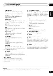
... system assign it to turn on this ). Use to the TV button (see page 54 for more on /off other components connected to the receiver (see page 53 for more on this ). 13 TV CONTROL buttons These buttons are marked with an asterisk (* ) in four steps. Use to set the...
... system assign it to turn on this ). Use to the TV button (see page 54 for more on /off other components connected to the receiver (see page 53 for more on this ). 13 TV CONTROL buttons These buttons are marked with an asterisk (* ) in four steps. Use to set the...
Owner's Manual
Page 18
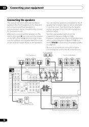
... on the speakers. Be sure to the right (R) terminal and the speaker on page 20. Also make sure the positive and negative (+/-) terminals on the receiver match those on page 20 for surround sound. You can use speakers with a normal impedance between 12 Ω and 16 Ω if you connect the... LOOP COMPONENT VIDEO IN 1 (BD) ASSIGNABLE 12 Class 2 Wiring L CENTER SW Powered subwoofer Speaker system B L R 18 En 03 Connecting your equipment Connecting the speakers The receiver will work with just two stereo speakers (the front speakers in another room.
... on the speakers. Be sure to the right (R) terminal and the speaker on page 20. Also make sure the positive and negative (+/-) terminals on the receiver match those on page 20 for surround sound. You can use speakers with a normal impedance between 12 Ω and 16 Ω if you connect the... LOOP COMPONENT VIDEO IN 1 (BD) ASSIGNABLE 12 Class 2 Wiring L CENTER SW Powered subwoofer Speaker system B L R 18 En 03 Connecting your equipment Connecting the speakers The receiver will work with just two stereo speakers (the front speakers in another room.

Owner's Manual
Page 20
... sound is heard from the speakers. If this happens, the magnetic field produced by the transformers in the proper direction. Sound is output from this receiver, for stereo output from the HDMI is 480i, 480p, 576i or 576p, Multi Ch PCM sound and HD sound cannot be... received. 20 En If connecting the player and the TV via this receiver). • If the video signal does not appear on your TV or flat panel TV, try adjusting the resolution...
... sound is heard from the speakers. If this happens, the magnetic field produced by the transformers in the proper direction. Sound is output from this receiver, for stereo output from the HDMI is 480i, 480p, 576i or 576p, Multi Ch PCM sound and HD sound cannot be... received. 20 En If connecting the player and the TV via this receiver). • If the video signal does not appear on your TV or flat panel TV, try adjusting the resolution...

Owner's Manual
Page 21
...connected, it may occur when switching between audio formats or beginning playback. • Turning on/off the device connected to this receiver.4 Coaxial digital audio cable Optical cable Video cables Standard RCA video cables These cables are the most common type of video connection ...and are trademarks of Sony Corporation. This receiver incorporates High-Definition Multimedia Interface (HDMI™) technology. "x.v.Color" and x.v.Color logo are used , it may not work properly. •...
...connected, it may occur when switching between audio formats or beginning playback. • Turning on/off the device connected to this receiver.4 Coaxial digital audio cable Optical cable Video cables Standard RCA video cables These cables are the most common type of video connection ...and are trademarks of Sony Corporation. This receiver incorporates High-Definition Multimedia Interface (HDMI™) technology. "x.v.Color" and x.v.Color logo are used , it may not work properly. •...

Owner's Manual
Page 22
... Terminal for connecting to the TV. In this unit will not appear. Component video cables Green (Y) Blue (PB) Red (PR) About video outputs connection This receiver is not loaded with TV monitor The OSD will not be output from the HDMI OUT. The color signal of your video source. 03 Connecting...
... Terminal for connecting to the TV. In this unit will not appear. Component video cables Green (Y) Blue (PB) Red (PR) About video outputs connection This receiver is not loaded with TV monitor The OSD will not be output from the HDMI OUT. The color signal of your video source. 03 Connecting...
Owner's Manual
Page 23
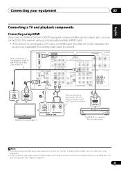
... IN 1 (BD) ASSIGNABLE 12 Class 2 Wiring L 2 VIDEO IN HDMI IN This connection is required in order to see the OSD of the TV over the receiver. Be sure to use a standard RCA analog video cable to connect.12 This connection is necessary in order to listen to the sound of the... be displayed.) 2 If the connection was made using an optical cable, you'll need to tell the receiver which digital input you can connect it to this receiver using a commercially available HDMI cable. • If the receiver is connected to a TV using HDMI If you have an HDMI or DVI (with HDCP) equipped...
... IN 1 (BD) ASSIGNABLE 12 Class 2 Wiring L 2 VIDEO IN HDMI IN This connection is required in order to see the OSD of the TV over the receiver. Be sure to use a standard RCA analog video cable to connect.12 This connection is necessary in order to listen to the sound of the... be displayed.) 2 If the connection was made using an optical cable, you'll need to tell the receiver which digital input you can connect it to this receiver using a commercially available HDMI cable. • If the receiver is connected to a TV using HDMI If you have an HDMI or DVI (with HDCP) equipped...
Owner's Manual
Page 24
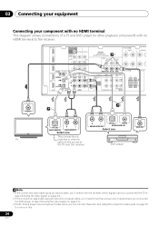
... your component with no HDMI terminal This diagram shows connections of a TV and DVD player (or other playback component) with no HDMI terminal to the receiver.123 IN BD DVD TV/SAT SUBWOOFER PRE OUT SURR BACK / FRONT HEIGHT L (Single) CD-R/TAPE DVR/VCR OUT R PRE OUT CD CD-R/TAPE DVR... ANALOG AUDIO OUT Select one DVD player VIDEO OUT Note 1 If the connection was made using an optical cable, you'll need to tell the receiver which digital input you connected the TV to (see Choosing the input signal on page 41). 2 If the connection was made using an optical or...
... your component with no HDMI terminal This diagram shows connections of a TV and DVD player (or other playback component) with no HDMI terminal to the receiver.123 IN BD DVD TV/SAT SUBWOOFER PRE OUT SURR BACK / FRONT HEIGHT L (Single) CD-R/TAPE DVR/VCR OUT R PRE OUT CD CD-R/TAPE DVR... ANALOG AUDIO OUT Select one DVD player VIDEO OUT Note 1 If the connection was made using an optical cable, you'll need to tell the receiver which digital input you connected the TV to (see Choosing the input signal on page 41). 2 If the connection was made using an optical or...

Owner's Manual
Page 25
...STB OPTICAL R PLAY L DIGITAL AUDIO OUT ANALOG AUDIO OUT Select one VIDEO OUT Connecting an HDD/DVD recorder, VCR and other video sources This receiver has audio/video inputs and outputs suitable for more on this too. See Connecting using an optical cable, you'll need to (see Choosing the...IN terminal can connect this . 25 En Connecting your equipment 03 English Deutsch Français Italiano Nederlands Español Connecting a satellite receiver or other digital set-top box Satellite and cable receivers, and terrestrial digital TV tuners are all examples of so-called 'set -
...STB OPTICAL R PLAY L DIGITAL AUDIO OUT ANALOG AUDIO OUT Select one VIDEO OUT Connecting an HDD/DVD recorder, VCR and other video sources This receiver has audio/video inputs and outputs suitable for more on this too. See Connecting using an optical cable, you'll need to (see Choosing the...IN terminal can connect this . 25 En Connecting your equipment 03 English Deutsch Français Italiano Nederlands Español Connecting a satellite receiver or other digital set-top box Satellite and cable receivers, and terrestrial digital TV tuners are all examples of so-called 'set -


