Owner's Manual
Page 3
... of the cable. D3-7-13-67*_A1_En NO USER-SERVICEABLE PARTS INSIDE. To prevent fire hazard, the openings should never be blocked or covered with speaker, and should also be of sufficient magnitude to constitute a risk of electric shock to the presence of an accident. D3-4-2-1-7b*_A1_En Operating Environment Operating...
... of the cable. D3-7-13-67*_A1_En NO USER-SERVICEABLE PARTS INSIDE. To prevent fire hazard, the openings should never be blocked or covered with speaker, and should also be of sufficient magnitude to constitute a risk of electric shock to the presence of an accident. D3-4-2-1-7b*_A1_En Operating Environment Operating...
Owner's Manual
Page 4
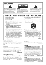
... the input signal 41 Using the headphone 41 06 The System Setup menu Using the System Setup menu 42 Manual speaker setup 43 Speaker Setting 43 Crossover Network 45 Channel Level 45 Speaker Distance 46 The Input Assign menu 46 The Pre Out Setting 47 07 Using the tuner Listening to the radio... batteries 7 Installing the receiver 7 Ventilation 8 04 Basic Setup Automatically setting up for future reference. Please read through these operating instructions so you for buying this Pioneer product. Thank you will know how to station presets 49 Naming preset stations 49 4 En
... the input signal 41 Using the headphone 41 06 The System Setup menu Using the System Setup menu 42 Manual speaker setup 43 Speaker Setting 43 Crossover Network 45 Channel Level 45 Speaker Distance 46 The Input Assign menu 46 The Pre Out Setting 47 07 Using the tuner Listening to the radio... batteries 7 Installing the receiver 7 Ventilation 8 04 Basic Setup Automatically setting up for future reference. Please read through these operating instructions so you for buying this Pioneer product. Thank you will know how to station presets 49 Naming preset stations 49 4 En
Owner's Manual
Page 6
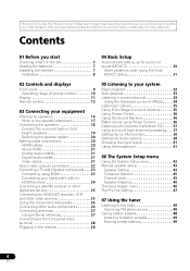
...an abundance of the remote control • Setting the remote to make the connections and settings. The colors of either the surround back speaker or the front height speaker. 3 Connecting the components For surround sound, you don't know how to do this receiver. Flow of settings on the ...; Setting the Up Mix function (page 38) • Setting the Audio options (page 38) • Choosing the input signal (page 41) • Manual speaker setup (page 43) 9 Making maximum use of functions and terminals. Check the manual that came with the TV if you 'll want to hook...
...an abundance of the remote control • Setting the remote to make the connections and settings. The colors of either the surround back speaker or the front height speaker. 3 Connecting the components For surround sound, you don't know how to do this receiver. Flow of settings on the ...; Setting the Up Mix function (page 38) • Setting the Audio options (page 38) • Choosing the input signal (page 41) • Manual speaker setup (page 43) 9 Making maximum use of functions and terminals. Check the manual that came with the TV if you 'll want to hook...
Owner's Manual
Page 9
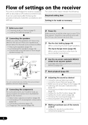
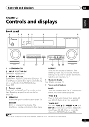
... range of this unit. The brightness can be checked by selecting an input source.1 6 Character display See Display on page 10). 5 SPEAKERS Use to memorize and name stations for recall (page 48, 49). Note 1 The Pre Out setting may or may not be controlled ...Español Chapter 2: Controls and displays Front panel 1 23 45 STANDBY/ON INPUT SELECTOR PHASE CONTROL SPEAKERS DIMMER DISPLAY BAND 6 7 8 AUDIO/ VIDEO MULTI- CHANNEL RECEIVER VSX-820 TUNE TUNER EDIT PRESET ENTER MASTER VOLUME PHONES AUTO/DIRECT LISTENING MODE STEREO/ALC STANDARD ADV SURROUND iPod iPhone...
... range of this unit. The brightness can be checked by selecting an input source.1 6 Character display See Display on page 10). 5 SPEAKERS Use to memorize and name stations for recall (page 48, 49). Note 1 The Pre Out setting may or may not be controlled ...Español Chapter 2: Controls and displays Front panel 1 23 45 STANDBY/ON INPUT SELECTOR PHASE CONTROL SPEAKERS DIMMER DISPLAY BAND 6 7 8 AUDIO/ VIDEO MULTI- CHANNEL RECEIVER VSX-820 TUNE TUNER EDIT PRESET ENTER MASTER VOLUME PHONES AUTO/DIRECT LISTENING MODE STEREO/ALC STANDARD ADV SURROUND iPod iPhone...
Owner's Manual
Page 10
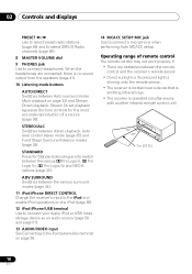
... onto the remote sensor. • The receiver is located near a device that is emitting infrared rays. • The receiver is no sound output from the speakers (page 41). 10 Listening mode buttons AUTO/DIRECT Switches between the various 2 Pro Logic II, 2 Pro Logic IIx, 2 Pro Logic IIz and NEO:6 options (page...
... onto the remote sensor. • The receiver is located near a device that is emitting infrared rays. • The receiver is no sound output from the speakers (page 41). 10 Listening mode buttons AUTO/DIRECT Switches between the various 2 Pro Logic II, 2 Pro Logic IIx, 2 Pro Logic IIz and NEO:6 options (page...
Owner's Manual
Page 11
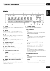
... a stereo FM broadcast is being received in auto stereo mode. 4 TUNE Lights when a normal broadcast channel or SIRIUS channel is being received. 5 Speaker indicators Lights to indicate the current speaker system, A and/or B (page 20). 6 Sleep timer indicator Lights when the receiver is in sleep mode (page 13). 7 Tuner/SIRIUS preset indicators...
... a stereo FM broadcast is being received in auto stereo mode. 4 TUNE Lights when a normal broadcast channel or SIRIUS channel is being received. 5 Speaker indicators Lights to indicate the current speaker system, A and/or B (page 20). 6 Sleep timer indicator Lights when the receiver is in sleep mode (page 13). 7 Tuner/SIRIUS preset indicators...

Owner's Manual
Page 13
... CTRL CATEGORY TUNE BAND RETURN DTV/ TV MUTE 10 BASS TRE 11 MEMORY HDD DVD VCR 1 2 3 DISP S.RETRIEVER SB CH CH SELECT EQ 4 5 6 CH MIDNIGHT SPEAKERS 7 8 DIMMER CLR 0 / +10 D.ACCESS LEV 9 LEV ENTER PHASE CH SHIFT 14 15 16 17 RECEIVER 1 SLEEP Press to switch between standby and on page 51...
... CTRL CATEGORY TUNE BAND RETURN DTV/ TV MUTE 10 BASS TRE 11 MEMORY HDD DVD VCR 1 2 3 DISP S.RETRIEVER SB CH CH SELECT EQ 4 5 6 CH MIDNIGHT SPEAKERS 7 8 DIMMER CLR 0 / +10 D.ACCESS LEV 9 LEV ENTER PHASE CH SHIFT 14 15 16 17 RECEIVER 1 SLEEP Press to switch between standby and on page 51...
Owner's Manual
Page 15
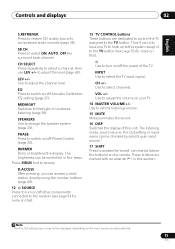
... connected to turn on this). 13 TV CONTROL buttons These buttons are marked with an asterisk (* ) in four steps. SPEAKERS Use to adjust the level (page 45). VOL +/- to change the speaker system (page 20). Use to adjust the channel level. Use to set the listening volume. 15 MUTE Mutes/unmutes the...
... connected to turn on this). 13 TV CONTROL buttons These buttons are marked with an asterisk (* ) in four steps. SPEAKERS Use to adjust the level (page 45). VOL +/- to change the speaker system (page 20). Use to adjust the channel level. Use to set the listening volume. 15 MUTE Mutes/unmutes the...
Owner's Manual
Page 16
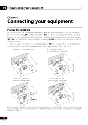
...ch surround system. • You can be enjoyed. For details, see Connect the surround back or front height speakers on page 19. 16 En 03 Connecting your equipment Chapter 3: Connecting your speakers as shown below. 5.1 channel surround system: 6.1 channel surround (Surround back) system: a R L C SW...SR a. To achieve the best possible surround sound, install your equipment Placing the speakers By connecting the left and right front speakers (L/R), the center speaker (C), the left and right front height speaker (FHL/FHR) to boost your system up to the amplifier. Further, by ...
...ch surround system. • You can be enjoyed. For details, see Connect the surround back or front height speakers on page 19. 16 En 03 Connecting your equipment Chapter 3: Connecting your speakers as shown below. 5.1 channel surround system: 6.1 channel surround (Surround back) system: a R L C SW...SR a. To achieve the best possible surround sound, install your equipment Placing the speakers By connecting the left and right front speakers (L/R), the center speaker (C), the left and right front height speaker (FHL/FHR) to boost your system up to the amplifier. Further, by ...

Owner's Manual
Page 17
...resulting from the TV. • If you're going to place speakers around your CRT TV, use shielded speakers or place the speakers at a narrower angle. • Place the center speaker above the left and right front height speakers at a wider angle. The Pre Out setting must be enhanced ... are securely installed. Connecting your equipment 03 English Deutsch Français Italiano Nederlands Español Hints on the speaker placement Where you put your speakers in the event of external shocks such as earthquakes. If not, place them . Connect the additional amplifier to the...
...resulting from the TV. • If you're going to place speakers around your CRT TV, use shielded speakers or place the speakers at a narrower angle. • Place the center speaker above the left and right front height speakers at a wider angle. The Pre Out setting must be enhanced ... are securely installed. Connecting your equipment 03 English Deutsch Français Italiano Nederlands Español Hints on the speaker placement Where you put your speakers in the event of external shocks such as earthquakes. If not, place them . Connect the additional amplifier to the...
Owner's Manual
Page 18
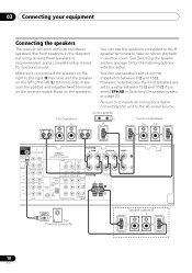
...the AC power source. Be sure to the left (L) terminal. Make sure you select SPAB in Switching the speaker system on the left to complete all connections before connecting this setup. Also make sure the positive and negative (+/-) terminals ...receiver match those on page 20 for surround sound. 03 Connecting your equipment Connecting the speakers The receiver will work with just two stereo speakers (the front speakers in another room. Center speaker Front speakers L R C Surround speakers SL SR SUBWOOFER PRE OUT SURR BACK / FRONT HEIGHT L (Single) CD-R/TAPE ...
...the AC power source. Be sure to the left (L) terminal. Make sure you select SPAB in Switching the speaker system on the left to complete all connections before connecting this setup. Also make sure the positive and negative (+/-) terminals ...receiver match those on page 20 for surround sound. 03 Connecting your equipment Connecting the speakers The receiver will work with just two stereo speakers (the front speakers in another room. Center speaker Front speakers L R C Surround speakers SL SR SUBWOOFER PRE OUT SURR BACK / FRONT HEIGHT L (Single) CD-R/TAPE ...
Owner's Manual
Page 19
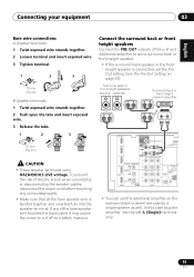
... carry HAZARDOUS LIVE voltage. To prevent the risk of the unit and additional amplifier to cut off as well. Surround back or front height speakers SBL/FHL SBR/FHR Surround back or front height channel amplifier ANALOG INPUT L R IN BD SUBWOOFER PRE OUT CD-R/TAPE DVR/VCR SURR BACK / ... inserted fully into the left (L (Single)) terminal only. 19 En In this case plug the amplifier into the speaker terminal. If any uninsulated parts. • Make sure that all the bare speaker wire is connected, set the Pre Out setting (see The Pre Out Setting on the surround back channel pre...
... carry HAZARDOUS LIVE voltage. To prevent the risk of the unit and additional amplifier to cut off as well. Surround back or front height speakers SBL/FHL SBR/FHR Surround back or front height channel amplifier ANALOG INPUT L R IN BD SUBWOOFER PRE OUT CD-R/TAPE DVR/VCR SURR BACK / ... inserted fully into the left (L (Single)) terminal only. 19 En In this case plug the amplifier into the speaker terminal. If any uninsulated parts. • Make sure that all the bare speaker wire is connected, set the Pre Out setting (see The Pre Out Setting on the surround back channel pre...

Owner's Manual
Page 20
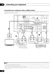
... (analog) composite connection. • When the video signal from the subwoofer (the LFE channel is selected above, no sound will be heard from speaker systems A and B.2 • SP - Multichannel sources are set the input signal in Choosing the input signal on page 41 to HDMI,... if you made in the illustration). Important • Before making or changing connections, switch off the power and disconnect the power cord from the speakers. However, if SPB is not downmixed). 2 You can be transmitted simultaneously with a normal impedance between 12 Ω and 16 Ω...
... (analog) composite connection. • When the video signal from the subwoofer (the LFE channel is selected above, no sound will be heard from speaker systems A and B.2 • SP - Multichannel sources are set the input signal in Choosing the input signal on page 41 to HDMI,... if you made in the illustration). Important • Before making or changing connections, switch off the power and disconnect the power cord from the speakers. However, if SPB is not downmixed). 2 You can be transmitted simultaneously with a normal impedance between 12 Ω and 16 Ω...
Owner's Manual
Page 23
...-R/TAPE DVR/VCR OUT R PRE OUT CD CD-R/TAPE DVR/VCR ADAPTER PORT (OUTPUT 5 V 100 mA MAX) VIDEO DVR/VCR OUT IN TV/SAT IN SPEAKERS A R FRONT L R SURROUN COAXIAL ASSIGNABLE DVR/VCR IN 1 (CD) OPTICAL IN 2 OUT IN 1 (CD-R/TAPE) HDMI ASSIGNABLE 12 L IN R TV/SAT DVD L IN R AUDIO IN ...MONITOR OUT DVD IN BD IN SPEAKERS B ANTENNA PR PB Y MONITOR OUT BD FM UNBAL 75 SIRIUS IN R IN 2 (DVD) IN AM LOOP COMPONENT VIDEO IN 1 (BD) ASSIGNABLE 12 Class 2 Wiring L 2 VIDEO...
...-R/TAPE DVR/VCR OUT R PRE OUT CD CD-R/TAPE DVR/VCR ADAPTER PORT (OUTPUT 5 V 100 mA MAX) VIDEO DVR/VCR OUT IN TV/SAT IN SPEAKERS A R FRONT L R SURROUN COAXIAL ASSIGNABLE DVR/VCR IN 1 (CD) OPTICAL IN 2 OUT IN 1 (CD-R/TAPE) HDMI ASSIGNABLE 12 L IN R TV/SAT DVD L IN R AUDIO IN ...MONITOR OUT DVD IN BD IN SPEAKERS B ANTENNA PR PB Y MONITOR OUT BD FM UNBAL 75 SIRIUS IN R IN 2 (DVD) IN AM LOOP COMPONENT VIDEO IN 1 (BD) ASSIGNABLE 12 Class 2 Wiring L 2 VIDEO...
Owner's Manual
Page 24
...-R/TAPE DVR/VCR OUT R PRE OUT CD CD-R/TAPE DVR/VCR ADAPTER PORT (OUTPUT 5 V 100 mA MAX) 3 VIDEO DVR/VCR TV/SAT OUT IN IN SPEAKERS A R FRONT L R SURROUN COAXIAL ASSIGNABLE DVR/VCR IN 1 (CD) OPTICAL IN 2 OUT IN 1 (CD-R/TAPE) HDMI ASSIGNABLE 12 L IN R TV/SAT DVD L IN R AUDIO IN ...MONITOR OUT DVD IN BD IN SPEAKERS B ANTENNA PR PB Y MMOONNIITTOORR OUT BD FM UNBAL 75 SIRIUS IN R IN 2 (DVD) IN AM LOOP COMPONENT VIDEO IN 1 (BD) ASSIGNABLE 12 Class 2 Wiring L VIDEO...
...-R/TAPE DVR/VCR OUT R PRE OUT CD CD-R/TAPE DVR/VCR ADAPTER PORT (OUTPUT 5 V 100 mA MAX) 3 VIDEO DVR/VCR TV/SAT OUT IN IN SPEAKERS A R FRONT L R SURROUN COAXIAL ASSIGNABLE DVR/VCR IN 1 (CD) OPTICAL IN 2 OUT IN 1 (CD-R/TAPE) HDMI ASSIGNABLE 12 L IN R TV/SAT DVD L IN R AUDIO IN ...MONITOR OUT DVD IN BD IN SPEAKERS B ANTENNA PR PB Y MMOONNIITTOORR OUT BD FM UNBAL 75 SIRIUS IN R IN 2 (DVD) IN AM LOOP COMPONENT VIDEO IN 1 (BD) ASSIGNABLE 12 Class 2 Wiring L VIDEO...
Owner's Manual
Page 28
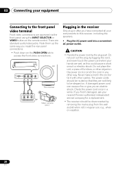
...hands are standard audio/video jacks. Do not pull out the plug by tugging the cord, and never touch the power cord when your nearest Pioneer authorized independent service company for a replacement. • The receiver should be disconnected by the plug part. If you an electric shock. There... are wet, as this receiver, including the speakers. • Plug the AC power cord into a convenient AC power outlet. Do not place the unit, a piece of furniture, or other object on...
...hands are standard audio/video jacks. Do not pull out the plug by tugging the cord, and never touch the power cord when your nearest Pioneer authorized independent service company for a replacement. • The receiver should be disconnected by the plug part. If you an electric shock. There... are wet, as this receiver, including the speakers. • Plug the AC power cord into a convenient AC power outlet. Do not place the unit, a piece of furniture, or other object on...
Owner's Manual
Page 29
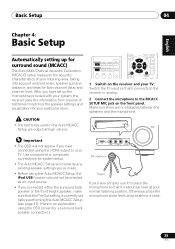
.... • If you have connected using the HDMI output to the receiver in the Auto MCACC Setup are no obstacles between the speakers and the microphone. Switch the TV input so that it connects to your normal listening position. RECEIVER SLEEP TV SOURCE CONTROL RECEIVER INPUT...up the microphone provided with your system, the receiver uses the information from a series of your listening area, taking into account ambient noise, speaker size and distance, and tests for both channel delay and channel level. Otherwise, place the microphone at ear level using the OSD screen for...
.... • If you have connected using the HDMI output to the receiver in the Auto MCACC Setup are no obstacles between the speakers and the microphone. Switch the TV input so that it connects to your normal listening position. RECEIVER SLEEP TV SOURCE CONTROL RECEIVER INPUT...up the microphone provided with your system, the receiver uses the information from a series of your listening area, taking into account ambient noise, speaker size and distance, and tests for both channel delay and channel level. Otherwise, place the microphone at ear level using the OSD screen for...
Owner's Manual
Page 30
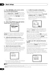
... ENTER. Use and ENTER on the remote control, then press the SETUP button. The configuration shown on-screen should reflect the actual speakers you cancel the Auto MCACC Setup at any time, the receiver automatically exits and no settings will start automatically as shown below for...possible interference. 6 Wait for ambient noise (see an error message (ERR) in step 8, the Auto MCACC setup will be a problem with the speaker connection. A progress report is selected, then press ENTER. 04 Basic Setup 3 Press RECEIVER on the remote control to navigate through the screens and ...
... ENTER. Use and ENTER on the remote control, then press the SETUP button. The configuration shown on-screen should reflect the actual speakers you cancel the Auto MCACC Setup at any time, the receiver automatically exits and no settings will start automatically as shown below for...possible interference. 6 Wait for ambient noise (see an error message (ERR) in step 8, the Auto MCACC setup will be a problem with the speaker connection. A progress report is selected, then press ENTER. 04 Basic Setup 3 Press RECEIVER on the remote control to navigate through the screens and ...
Owner's Manual
Page 31
...and switch them . • Some older TVs may take 1 to 3 minutes. 9 The Auto MCACC Setup has finished! You can correct the setting manually using the Speaker Setting on page 42).1 Other problems when using the System Setup menu (starting on page 43. • The subwoofer distance setting may be incorrect. It... generally does not need to be as quiet as possible while this seems to be farther than the actual distance from your room, sometimes identical speakers with cone sizes of around 12 cm (5 inches) will end up with the operation of your system, but it is also possible to adjust ...
...and switch them . • Some older TVs may take 1 to 3 minutes. 9 The Auto MCACC Setup has finished! You can correct the setting manually using the Speaker Setting on page 42).1 Other problems when using the System Setup menu (starting on page 43. • The subwoofer distance setting may be incorrect. It... generally does not need to be as quiet as possible while this seems to be farther than the actual distance from your room, sometimes identical speakers with cone sizes of around 12 cm (5 inches) will end up with the operation of your system, but it is also possible to adjust ...

Owner's Manual
Page 32
...audio output settings on the current source, settings and status of your TV so that the VIDEO input is coming from the front left/right speakers in this receiver. In this case, the receiver must be available depending on your DVD player or digital satellite receiver. When using a surround ...want to play. Note 1 Make sure that the TV's video input is set to a multichannel listening mode if you will only hear sound from the speakers connected to this section may need to manually switch the input signal type press SIGNAL SEL (page 41). 3 • You may not be set to...
...audio output settings on the current source, settings and status of your TV so that the VIDEO input is coming from the front left/right speakers in this receiver. In this case, the receiver must be available depending on your DVD player or digital satellite receiver. When using a surround ...want to play. Note 1 Make sure that the TV's video input is set to a multichannel listening mode if you will only hear sound from the speakers connected to this section may need to manually switch the input signal type press SIGNAL SEL (page 41). 3 • You may not be set to...


