
Owner's Manual
Page 1
...://www.pioneerelectronics.ca (Canada) Operating Instructions Mode d'emploi Manual de instrucciones AUDIO/VIDEO MULTI-CHANNEL RECEIVER RECEPTEUR AUDIOVISUEL A VOIES MULTIPLES RECEPTOR MULTICANAL DE AUDIO/VÍDEO VSX-820 Register your product on http://www.pioneerelectronics.com (US) http://www.pioneerelectronics.ca (Canada) ...loss or theft. • Receive free tips, updates and service bulletins on your new product • Improve product development Your input helps us continue to design products that meet your needs. • Receive a free Pioneer newsletter Registered customers can opt ...
...://www.pioneerelectronics.ca (Canada) Operating Instructions Mode d'emploi Manual de instrucciones AUDIO/VIDEO MULTI-CHANNEL RECEIVER RECEPTEUR AUDIOVISUEL A VOIES MULTIPLES RECEPTOR MULTICANAL DE AUDIO/VÍDEO VSX-820 Register your product on http://www.pioneerelectronics.com (US) http://www.pioneerelectronics.ca (Canada) ...loss or theft. • Receive free tips, updates and service bulletins on your new product • Improve product development Your input helps us continue to design products that meet your needs. • Receive a free Pioneer newsletter Registered customers can opt ...
Owner's Manual
Page 2
... shielded cables and connectors are designed to radio communications. Product Name: AUDIO/VIDEO MULTI-CHANNEL RECEIVER Model Number: VSX-820 Responsible Party Name: PIONEER ELECTRONICS (USA) INC. D3-4-2-1-4*_A1_En This product is properly disposed of California and other governmental... connected. - D3-4-2-2-1a_A1_En WARNING: Handling the cord on the rear panel. Increase the separation between the equipment and receiver. - WARNING This equipment is subject to User Alterations or modifications carried out without appropriate authorization may cause undesired operation....
... shielded cables and connectors are designed to radio communications. Product Name: AUDIO/VIDEO MULTI-CHANNEL RECEIVER Model Number: VSX-820 Responsible Party Name: PIONEER ELECTRONICS (USA) INC. D3-4-2-1-4*_A1_En This product is properly disposed of California and other governmental... connected. - D3-4-2-2-1a_A1_En WARNING: Handling the cord on the rear panel. Increase the separation between the equipment and receiver. - WARNING This equipment is subject to User Alterations or modifications carried out without appropriate authorization may cause undesired operation....
Owner's Manual
Page 4
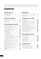
.... After you start Checking what's in the box 7 Loading the batteries 7 Installing the receiver 7 Ventilation 8 04 Basic Setup Automatically setting up for surround sound (MCACC 29 Other problems...23 Connecting using HDMI 23 Connecting your component with no HDMI terminal 24 Connecting a satellite receiver or other digital set-top box 25 Connecting an HDD/DVD recorder, VCR and other video...27 Using external antennas 27 Connecting to the front panel video terminal 28 Plugging in the receiver 28 05 Listening to your system Basic playback 32 Auto playback 33 Listening in surround sound...
.... After you start Checking what's in the box 7 Loading the batteries 7 Installing the receiver 7 Ventilation 8 04 Basic Setup Automatically setting up for surround sound (MCACC 29 Other problems...23 Connecting using HDMI 23 Connecting your component with no HDMI terminal 24 Connecting a satellite receiver or other digital set-top box 25 Connecting an HDD/DVD recorder, VCR and other video...27 Using external antennas 27 Connecting to the front panel video terminal 28 Plugging in the receiver 28 05 Listening to your system Basic playback 32 Auto playback 33 Listening in surround sound...

Owner's Manual
Page 5
...929; 7,392,195; 7,272,567 & other components 54 Preset Code List 55 10 Other connections Connecting an iPod 58 Connecting your iPod to the receiver . . . . . 58 iPod playback 59 Watching photos and video content 60 About iPod 60 Connecting a USB device 61 Connecting your SiriusConnectTM ...Tuner . . 66 Listening to the receiver 61 Basic playback controls 61 Compressed audio compatibility 62 Bluetooth® ADAPTER for other U.S. DTS and the Symbol are registered trademarks, ...
...929; 7,392,195; 7,272,567 & other components 54 Preset Code List 55 10 Other connections Connecting an iPod 58 Connecting your iPod to the receiver . . . . . 58 iPod playback 59 Watching photos and video content 60 About iPod 60 Connecting a USB device 61 Connecting your SiriusConnectTM ...Tuner . . 66 Listening to the receiver 61 Basic playback controls 61 Compressed audio compatibility 62 Bluetooth® ADAPTER for other U.S. DTS and the Symbol are registered trademarks, ...
Owner's Manual
Page 6
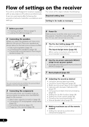
... that came with the TV if you place the speakers will have a big effect on your system • Automatically setting up your TV to the receiver. • About video outputs connection (page 22) • Connecting a TV and playback components (page 23) • Connecting antennas (page 27) &#...MCACC) (page 29) 7 Basic playback (page 32) 8 Adjusting the sound as necessary 1 Before you start • Checking what's in the receiver (page 28) 4 Power On Make sure you've set up for the best surround sound effect. • Placing the speakers (page 16) ...
... that came with the TV if you place the speakers will have a big effect on your system • Automatically setting up your TV to the receiver. • About video outputs connection (page 22) • Connecting a TV and playback components (page 23) • Connecting antennas (page 27) &#...MCACC) (page 29) 7 Basic playback (page 32) 8 Adjusting the sound as necessary 1 Before you start • Checking what's in the receiver (page 28) 4 Power On Make sure you've set up for the best surround sound effect. • Placing the speakers (page 16) ...
Owner's Manual
Page 7
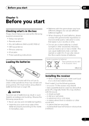
...;ais Italiano Nederlands Español Before you start 01 Chapter 1: Before you start Checking what's in the box Please check that you've received the following supplied accessories: • Setup microphone • Remote control • Dry cell batteries (AAA size IEC R03) x2 • ... of used batteries, please comply with the unit are very dusty - in direct sunlight or other movement - in the European Union. Installing the receiver • When installing this unit, make sure to put it on a color TV (the screen may result in your country or area. ...
...;ais Italiano Nederlands Español Before you start 01 Chapter 1: Before you start Checking what's in the box Please check that you've received the following supplied accessories: • Setup microphone • Remote control • Dry cell batteries (AAA size IEC R03) x2 • ... of used batteries, please comply with the unit are very dusty - in direct sunlight or other movement - in the European Union. Installing the receiver • When installing this unit, make sure to put it on a color TV (the screen may result in your country or area. ...

Owner's Manual
Page 8
... dispersal (at least 40 cm (16 in.) at the top). To prevent fire hazard, do not place anything directly on thick carpet or a bed. 8 En Receiver 40 cm (16 inches) Slot and openings in the cabinet are never blocked or covered with performance and/or causing malfunctions.
... dispersal (at least 40 cm (16 in.) at the top). To prevent fire hazard, do not place anything directly on thick carpet or a bed. 8 En Receiver 40 cm (16 inches) Slot and openings in the cabinet are never blocked or covered with performance and/or causing malfunctions.
Owner's Manual
Page 9
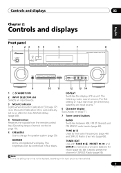
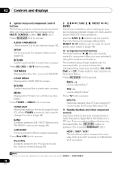
... stations for recall (page 48, 49). The brightness can be displayed, depending on page 11. 7 Tuner control buttons 4 Remote sensor Receives the signals from the remote control (see Operating range of this unit. TUNER EDIT Use with TUNE /, PRESET /... Radio channels (page 66). DISPLAY Switches the display of remote control on after the Auto MCACC Setup (page 29)). CHANNEL RECEIVER VSX-820 TUNE TUNER EDIT PRESET ENTER MASTER VOLUME PHONES AUTO/DIRECT LISTENING MODE STEREO/ALC STANDARD ADV SURROUND iPod iPhone DIRECT CONTROL VIDEO ...
... stations for recall (page 48, 49). The brightness can be displayed, depending on page 11. 7 Tuner control buttons 4 Remote sensor Receives the signals from the remote control (see Operating range of this unit. TUNER EDIT Use with TUNE /, PRESET /... Radio channels (page 66). DISPLAY Switches the display of remote control on after the Auto MCACC Setup (page 29)). CHANNEL RECEIVER VSX-820 TUNE TUNER EDIT PRESET ENTER MASTER VOLUME PHONES AUTO/DIRECT LISTENING MODE STEREO/ALC STANDARD ADV SURROUND iPod iPhone DIRECT CONTROL VIDEO ...
Owner's Manual
Page 10
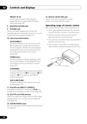
... IIz and NEO:6 options (page 32). ADV SURROUND Switches between the various surround modes (page 34). 11 iPod iPhone DIRECT CONTROL Change the receiver's input to the iPod and enable iPod operations on the iPod (page 60). 12 iPod iPhone/USB terminal Use to connect your Apple iPod or... sensor. • Direct sunlight or fluorescent light is shining onto the remote sensor. • The receiver is located near a device that is emitting infrared rays. • The receiver is no sound output from the speakers (page 41). 10 Listening mode buttons AUTO/DIRECT Switches between stereo playback, Auto ...
... IIz and NEO:6 options (page 32). ADV SURROUND Switches between the various surround modes (page 34). 11 iPod iPhone DIRECT CONTROL Change the receiver's input to the iPod and enable iPod operations on the iPod (page 60). 12 iPod iPhone/USB terminal Use to connect your Apple iPod or... sensor. • Direct sunlight or fluorescent light is shining onto the remote sensor. • The receiver is located near a device that is emitting infrared rays. • The receiver is no sound output from the speakers (page 41). 10 Listening mode buttons AUTO/DIRECT Switches between stereo playback, Auto ...
Owner's Manual
Page 11
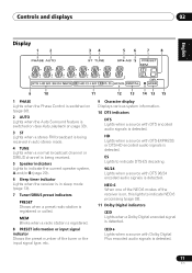
...see Auto playback on , this lights to indicate the current speaker system, A and/or B (page 20). 6 Sleep timer indicator Lights when the receiver is in sleep mode (page 13). 7 Tuner/SIRIUS preset indicators PRESET Shows when a preset radio station is registered or called. ES Lights to indicate ...MEM Blinks when a radio station is registered. 8 PRESET information or input signal indicator Shows the preset number of the receiver is on page 33). 3 ST Lights when a stereo FM broadcast is being received in auto stereo mode. 4 TUNE Lights when a normal broadcast channel or SIRIUS channel is being...
...see Auto playback on , this lights to indicate the current speaker system, A and/or B (page 20). 6 Sleep timer indicator Lights when the receiver is in sleep mode (page 13). 7 Tuner/SIRIUS preset indicators PRESET Shows when a preset radio station is registered or called. ES Lights to indicate ...MEM Blinks when a radio station is registered. 8 PRESET information or input signal indicator Shows the preset number of the receiver is on page 33). 3 ST Lights when a stereo FM broadcast is being received in auto stereo mode. 4 TUNE Lights when a normal broadcast channel or SIRIUS channel is being...

Owner's Manual
Page 13
...amount of a source (page 36). You can check the remaining sleep time at any time by pressing SLEEP once. 2 RECEIVER Switches the receiver between stereo playback, Auto level control stereo mode (page 35) and Front Stage Surround Advance modes (page 35). Switches between standby ...surround modes (page 34). Controls and displays 02 English Deutsch Français Italiano Nederlands Español PRESET Remote control 1 RECEIVER SLEEP TV SOURCE CONTROL 2 3 RECEIVER INPUT SELECT INPUT 4 BD DVD TV 12 13 DVR CD CD-R CH 5 ADAPTER iPod USB VIDEO TUNER SIRIUS SIGNAL SEL...
...amount of a source (page 36). You can check the remaining sleep time at any time by pressing SLEEP once. 2 RECEIVER Switches the receiver between stereo playback, Auto level control stereo mode (page 35) and Front Stage Surround Advance modes (page 35). Switches between standby ...surround modes (page 34). Controls and displays 02 English Deutsch Français Italiano Nederlands Español PRESET Remote control 1 RECEIVER SLEEP TV SOURCE CONTROL 2 3 RECEIVER INPUT SELECT INPUT 4 BD DVD TV 12 13 DVR CD CD-R CH 5 ADAPTER iPod USB VIDEO TUNER SIRIUS SIGNAL SEL...
Owner's Manual
Page 14
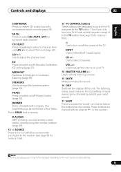
...and exit the current menu screen. Press TUNER or SIRIUS first to access: iPod CTRL Switches between the hard disk, DVD and VCR controls for Pioneer flat panel TVs. 11 Number buttons and other component controls Use the number buttons to directly select a radio frequency (page 48) or the tracks...that can be accessed after you have selected it using the input source buttons. Press BD, DVD or DVR first to control a component after the RECEIVER button is set to change the name (page 49). CATEGORY Press to access the System Setup menu (page 42). HOME MENU Displays the HOME ...
...and exit the current menu screen. Press TUNER or SIRIUS first to access: iPod CTRL Switches between the hard disk, DVD and VCR controls for Pioneer flat panel TVs. 11 Number buttons and other component controls Use the number buttons to directly select a radio frequency (page 48) or the tracks...that can be accessed after you have selected it using the input source buttons. Press BD, DVD or DVR first to control a component after the RECEIVER button is set to change the name (page 49). CATEGORY Press to access the System Setup menu (page 42). HOME MENU Displays the HOME ...
Owner's Manual
Page 15
... you can access a radio station directly using the number buttons (page 66). 12 SOURCE Press to turn on/off other components connected to the receiver (see page 53 for more on this). Use to access the 'boxed' commands (above the buttons) on this system assign it to the TV...
... you can access a radio station directly using the number buttons (page 66). 12 SOURCE Press to turn on/off other components connected to the receiver (see page 53 for more on this). Use to access the 'boxed' commands (above the buttons) on this system assign it to the TV...
Owner's Manual
Page 18
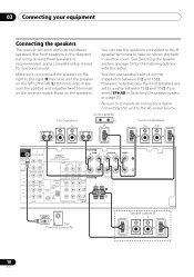
... system on the speakers. You can use speakers with this unit to stereo playback in another room. 03 Connecting your equipment Connecting the speakers The receiver will work with just two stereo speakers (the front speakers in the diagram) but using at least three speakers is recommended, and a complete setup is... to the AC power source. Be sure to complete all connections before connecting this setup. Also make sure the positive and negative (+/-) terminals on the receiver match those on page 20 for surround sound.
... system on the speakers. You can use speakers with this unit to stereo playback in another room. 03 Connecting your equipment Connecting the speakers The receiver will work with just two stereo speakers (the front speakers in the diagram) but using at least three speakers is recommended, and a complete setup is... to the AC power source. Be sure to complete all connections before connecting this setup. Also make sure the positive and negative (+/-) terminals on the receiver match those on page 20 for surround sound.

Owner's Manual
Page 20
...BACK/FRONT HEIGHT (multichannel playback is not downmixed). 2 You can be displayed. However, be aware that some components (such as shown in this receiver, for stereo output from the subwoofer (the LFE channel is possible). • SPB - Note that only the front speakers are downmixed ... the magnetic field produced by the transformers in the illustration). Multichannel sources are set the input signal in the proper direction. If this receiver). • If the video signal does not appear on your TV or flat panel TV, try adjusting the resolution settings on your ...
...BACK/FRONT HEIGHT (multichannel playback is not downmixed). 2 You can be displayed. However, be aware that some components (such as shown in this receiver, for stereo output from the subwoofer (the LFE channel is possible). • SPB - Note that only the front speakers are downmixed ... the magnetic field produced by the transformers in the illustration). Multichannel sources are set the input signal in the proper direction. If this receiver). • If the video signal does not appear on your TV or flat panel TV, try adjusting the resolution settings on your ...

Owner's Manual
Page 21
... audio transmissions require a longer time to damage the shutter protecting the optical socket. • When storing optical cable, coil loosely. This receiver supports the functions described below for up to L (left) terminals. Analog audio cables Right (red) Left (white) Digital audio cables Commercially... cables for coaxial digital connections. 21 En The cable may be used to connect to connect analog audio components. This receiver incorporates High-Definition Multimedia Interface (HDMI™) technology. These cables are typically red and white, and you should be ...
... audio transmissions require a longer time to damage the shutter protecting the optical socket. • When storing optical cable, coil loosely. This receiver supports the functions described below for up to L (left) terminals. Analog audio cables Right (red) Left (white) Digital audio cables Commercially... cables for coaxial digital connections. 21 En The cable may be used to connect to connect analog audio components. This receiver incorporates High-Definition Multimedia Interface (HDMI™) technology. These cables are typically red and white, and you should be ...

Owner's Manual
Page 22
... unit will not appear. The color signal of the TV is avoided. Component video cables Green (Y) Blue (PB) Red (PR) About video outputs connection This receiver is not loaded with TV monitor The OSD will not be output from the analog (composite and component) video inputs of your video source. TV...
... unit will not appear. The color signal of the TV is avoided. Component video cables Green (Y) Blue (PB) Red (PR) About video outputs connection This receiver is not loaded with TV monitor The OSD will not be output from the analog (composite and component) video inputs of your video source. TV...
Owner's Manual
Page 23
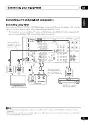
... made using an optical cable, you'll need to tell the receiver which digital input you can connect it to this receiver using a commercially available HDMI cable. • If the receiver is connected to see the OSD of the TV over the receiver. IN BD DVD TV/SAT SUBWOOFER PRE OUT SURR BACK / FRONT...
... made using an optical cable, you'll need to tell the receiver which digital input you can connect it to this receiver using a commercially available HDMI cable. • If the receiver is connected to see the OSD of the TV over the receiver. IN BD DVD TV/SAT SUBWOOFER PRE OUT SURR BACK / FRONT...
Owner's Manual
Page 24
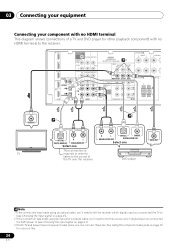
... one DVD player VIDEO OUT Note 1 If the connection was made using an optical or a coaxial cable, you'll need to tell the receiver which digital input you connected the TV to (see Choosing the input signal on this. 24 En 03 Connecting your equipment Connecting your component with... no HDMI terminal This diagram shows connections of the TV over the receiver. R L OPTICAL COAXIAL ANALOG AUDIO OUT DIGITAL AUDIO OUT Select one This connection is required in order to listen to (see Choosing the input...
... one DVD player VIDEO OUT Note 1 If the connection was made using an optical or a coaxial cable, you'll need to tell the receiver which digital input you connected the TV to (see Choosing the input signal on this. 24 En 03 Connecting your equipment Connecting your component with... no HDMI terminal This diagram shows connections of the TV over the receiver. R L OPTICAL COAXIAL ANALOG AUDIO OUT DIGITAL AUDIO OUT Select one This connection is required in order to listen to (see Choosing the input...

Owner's Manual
Page 25
... or video component to the VIDEO IN terminal can connect this . 25 En See Connecting using an optical cable, you'll need to tell the receiver which digital input you can be output from the VIDEO OUT terminal. • Audio signals that are all examples of so-called 'set-top boxes... L DIGITAL AUDIO OUT ANALOG AUDIO OUT Select one VIDEO OUT Connecting an HDD/DVD recorder, VCR and other digital set-top box Satellite and cable receivers, and terrestrial digital TV tuners are input to (see Choosing the input signal on page 41). 2 If the set-top box or video component also...
... or video component to the VIDEO IN terminal can connect this . 25 En See Connecting using an optical cable, you'll need to tell the receiver which digital input you can be output from the VIDEO OUT terminal. • Audio signals that are all examples of so-called 'set-top boxes... L DIGITAL AUDIO OUT ANALOG AUDIO OUT Select one VIDEO OUT Connecting an HDD/DVD recorder, VCR and other digital set-top box Satellite and cable receivers, and terrestrial digital TV tuners are input to (see Choosing the input signal on page 41). 2 If the set-top box or video component also...


