Manual
Page 1
GA-H55M-S2H LGA1156 socket motherboard for Intel® Core™ i7 processor family/ Intel® Core™ i5 processor family/ Intel® Core™ i3 processor family User's Manual Rev. 1001 12ME-H55MS2H-1001R
GA-H55M-S2H LGA1156 socket motherboard for Intel® Core™ i7 processor family/ Intel® Core™ i5 processor family/ Intel® Core™ i3 processor family User's Manual Rev. 1001 12ME-H55MS2H-1001R
Manual
Page 2
Motherboard GA-H55M-S2H Dec. 7, 2009 Motherboard GA-H55M-S2H Dec. 7, 2009
Motherboard GA-H55M-S2H Dec. 7, 2009 Motherboard GA-H55M-S2H Dec. 7, 2009
Manual
Page 3
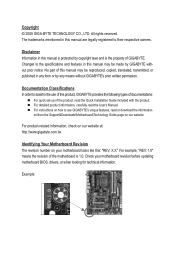
...this : "REV: X.X." For product-related information, check on our website at: http://www.gigabyte.com.tw Identifying Your Motherboard Revision The revision number on your motherboard revision before updating motherboard BIOS, drivers, or when looking for technical information. For instructions on our website. Example:... download the information on/from the Support&Downloads\Motherboard\Technology Guide page on how to assist in this product, GIGABYTE provides the following types of documentations: For quick set-up of the motherboard is the property of this manual may be made...
...this : "REV: X.X." For product-related information, check on our website at: http://www.gigabyte.com.tw Identifying Your Motherboard Revision The revision number on your motherboard revision before updating motherboard BIOS, drivers, or when looking for technical information. For instructions on our website. Example:... download the information on/from the Support&Downloads\Motherboard\Technology Guide page on how to assist in this product, GIGABYTE provides the following types of documentations: For quick set-up of the motherboard is the property of this manual may be made...
Manual
Page 4
Table of Contents Box Contents...6 Optional Items...6 GA-H55M-S2H Motherboard Layout 7 Block Diagram...8 Chapter 1 Hardware Installation 9 1-1 Installation Precautions 9 1-2 Product Specifications 10 1-3 Installing the CPU and CPU Cooler 13 1-3-1 Installing the CPU 13 1-3-2 Installing the CPU ...
Table of Contents Box Contents...6 Optional Items...6 GA-H55M-S2H Motherboard Layout 7 Block Diagram...8 Chapter 1 Hardware Installation 9 1-1 Installation Precautions 9 1-2 Product Specifications 10 1-3 Installing the CPU and CPU Cooler 13 1-3-1 Installing the CPU 13 1-3-2 Installing the CPU ...
Manual
Page 6
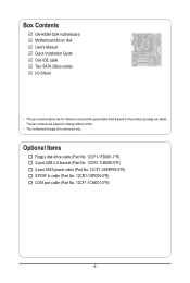
Box Contents GA-H55M-S2H motherboard Motherboard driver disk User's Manual Quick Installation Guide One IDE cable Two SATA 3Gb/s cables I/O Shield • The box contents above are subject to change without notice. • The motherboard image is for reference only and the actual items shall depend on the product package you obtain. The box contents are...
Box Contents GA-H55M-S2H motherboard Motherboard driver disk User's Manual Quick Installation Guide One IDE cable Two SATA 3Gb/s cables I/O Shield • The box contents above are subject to change without notice. • The motherboard image is for reference only and the actual items shall depend on the product package you obtain. The box contents are...
Manual
Page 7
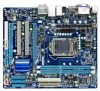
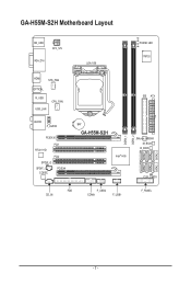
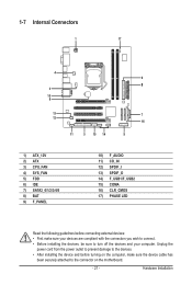
GA-H55M-S2H Motherboard Layout KB_USB ATX_12V VGA_DVI LGA1156 PHASE LED IT8720 HDMI SYS_FAN OPTICAL R_USB USB_LAN CPU_FAN AUDIO F_AUDIO PCIEX16 PCI1 RTL8111D PCI2 SPDIF_O SPDIF_I CODEC PCIEX4 IDE ATX BAT GA-H55M-S2H Intel® H55 JMicron JMB368 M_BIOS B_BIOS CLR_CMOS FDD CD_IN F_USB2 COMA F_USB1 F_PANEL DDR3_1 DDR3_2 SATA2_5 SATA2_2 SATA2_4 SATA2_1 SATA2_3 SATA2_0 - 7 -
GA-H55M-S2H Motherboard Layout KB_USB ATX_12V VGA_DVI LGA1156 PHASE LED IT8720 HDMI SYS_FAN OPTICAL R_USB USB_LAN CPU_FAN AUDIO F_AUDIO PCIEX16 PCI1 RTL8111D PCI2 SPDIF_O SPDIF_I CODEC PCIEX4 IDE ATX BAT GA-H55M-S2H Intel® H55 JMicron JMB368 M_BIOS B_BIOS CLR_CMOS FDD CD_IN F_USB2 COMA F_USB1 F_PANEL DDR3_1 DDR3_2 SATA2_5 SATA2_2 SATA2_4 SATA2_1 SATA2_3 SATA2_0 - 7 -
Manual
Page 9
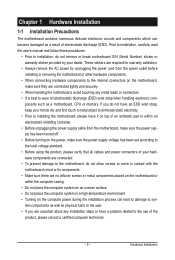
.... • Always remove the AC power by your dealer. If you are connected tightly and securely. • When handling the motherboard, avoid touching any installation steps or have it on top of an antistatic pad or within an electrostatic shielding container. • Before... unplugging the power supply cable from the power outlet before installing or removing the motherboard or other hardware components. • When connecting hardware components to the internal connectors on the computer power during the installation process ...
.... • Always remove the AC power by your dealer. If you are connected tightly and securely. • When handling the motherboard, avoid touching any installation steps or have it on top of an antistatic pad or within an electrostatic shielding container. • Before... unplugging the power supply cable from the power outlet before installing or removing the motherboard or other hardware components. • When connecting hardware components to the internal connectors on the computer power during the installation process ...
Manual
Page 12
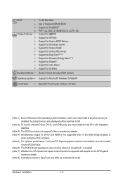
... CPU/system fan speed control function is supported will depend on the CPU/system cooler you install. (Note 8) Available functions in EasyTune may differ by motherboard model.
... CPU/system fan speed control function is supported will depend on the CPU/system cooler you install. (Note 8) Available functions in EasyTune may differ by motherboard model.
Manual
Page 13
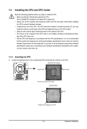
... for the latest CPU support list.) • Always turn on the computer if the CPU cooler is not recommended that the motherboard supports the CPU. (Go to GIGABYTE's website for the peripherals. If you wish to set beyond the standard specifications, please do so according to your hardware specifications...Locate the pin one of the CPU Socket LGA1156 CPU Notch Notch Triangle Pin One Marking on the CPU. Locate the alignment keys on the motherboard CPU socket and the notches on the CPU - 13 - 1-3 Installing the CPU and CPU Cooler Read the following guidelines before you begin ...
... for the latest CPU support list.) • Always turn on the computer if the CPU cooler is not recommended that the motherboard supports the CPU. (Go to GIGABYTE's website for the peripherals. If you wish to set beyond the standard specifications, please do so according to your hardware specifications...Locate the pin one of the CPU Socket LGA1156 CPU Notch Notch Triangle Pin One Marking on the CPU. Locate the alignment keys on the motherboard CPU socket and the notches on the CPU - 13 - 1-3 Installing the CPU and CPU Cooler Read the following guidelines before you begin ...
Manual
Page 14
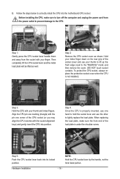
... as well. NOTE: Hold the CPU socket lever by the handle, not the lever base portion. Step 5: Push the CPU socket lever back into the motherboard CPU socket. Follow the steps below to the "REMOVE" mark) and then remove the cover. (DO NOT touch socket contacts. B.
... as well. NOTE: Hold the CPU socket lever by the handle, not the lever base portion. Step 5: Push the CPU socket lever back into the motherboard CPU socket. Follow the steps below to the "REMOVE" mark) and then remove the cover. (DO NOT touch socket contacts. B.
Manual
Page 15
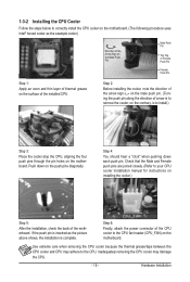
...instructions on installing the cooler.) Step 5: After the installation, check the back of arrow is to correctly install the CPU cooler on the motherboard. (The following procedure uses Intel® boxed cooler as the picture above shows, the installation is to the CPU. Inadequately removing the ...CPU cooler may adhere to install.) Step 3: Place the cooler atop the CPU, aligning the four push pins through the pin holes on the motherboard. Step 4: You should hear a "click" when pushing down on the push pins diagonally. Hardware Installation Step 2: Before installing the cooler, note...
...instructions on installing the cooler.) Step 5: After the installation, check the back of arrow is to correctly install the CPU cooler on the motherboard. (The following procedure uses Intel® boxed cooler as the picture above shows, the installation is to the CPU. Inadequately removing the ...CPU cooler may adhere to install.) Step 3: Place the cooler atop the CPU, aligning the four push pins through the pin holes on the motherboard. Step 4: You should hear a "click" when pushing down on the push pins diagonally. Hardware Installation Step 2: Before installing the cooler, note...
Manual
Page 16
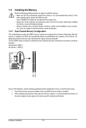
...; Make sure that memory of the same capacity, brand, speed, and chips be used . (Go to GIGABYTE's website for optimum performance. When enabling Dual Channel mode with two memory modules, it is recommended that the motherboard supports the memory. It is recommended that memory of the same capacity, brand, speed, and chips... each channel has one memory socket as following guidelines before installing the memory to insert the memory, switch the direction. 1-4-1 Dual Channel Memory Configuration This motherboard provides two DDR3 memory sockets and supports Dual Channel Technology.
...; Make sure that memory of the same capacity, brand, speed, and chips be used . (Go to GIGABYTE's website for optimum performance. When enabling Dual Channel mode with two memory modules, it is recommended that the motherboard supports the memory. It is recommended that memory of the same capacity, brand, speed, and chips... each channel has one memory socket as following guidelines before installing the memory to insert the memory, switch the direction. 1-4-1 Dual Channel Memory Configuration This motherboard provides two DDR3 memory sockets and supports Dual Channel Technology.
Manual
Page 17
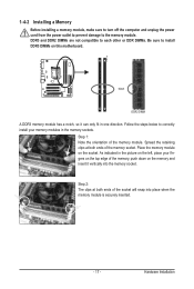
... of the socket will snap into the memory socket. Step 2: The clips at both ends of the memory module. Place the memory module on this motherboard. As indicated in one direction. Hardware Installation Spread the retaining clips at both ends of the memory, push down on the top edge of the...
... of the socket will snap into the memory socket. Step 2: The clips at both ends of the memory module. Place the memory module on this motherboard. As indicated in one direction. Hardware Installation Spread the retaining clips at both ends of the memory, push down on the top edge of the...
Manual
Page 18
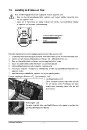
... driver provided with a screw. 5. PCI Express x16 Slot (PCIEX16/PCIEX4) PCI Slot Follow the steps below to install an expansion card: • Make sure the motherboard supports the expansion card. After installing all expansion cards, replace the chassis cover(s). 6. 1-5 Installing an Expansion Card Read the following guidelines before installing an expansion...
... driver provided with a screw. 5. PCI Express x16 Slot (PCIEX16/PCIEX4) PCI Slot Follow the steps below to install an expansion card: • Make sure the motherboard supports the expansion card. After installing all expansion cards, replace the chassis cover(s). 6. 1-5 Installing an Expansion Card Read the following guidelines before installing an expansion...
Manual
Page 20
... in jack ( ). Refer to the instructions on setting up to connect side speakers in a 5.1/7.1-channel audio configuration. Do not rock it straight out from the motherboard. • When removing the cable, pull it side to side to a back panel connector, first remove the cable from your device and then remove it...
... in jack ( ). Refer to the instructions on setting up to connect side speakers in a 5.1/7.1-channel audio configuration. Do not rock it straight out from the motherboard. • When removing the cable, pull it side to side to a back panel connector, first remove the cable from your device and then remove it...
Manual
Page 21
..., make sure your devices are compliant with the connectors you wish to connect. • Before installing the devices, be sure to the connector on the motherboard. - 21 -
..., make sure your devices are compliant with the connectors you wish to connect. • Before installing the devices, be sure to the connector on the motherboard. - 21 -
Manual
Page 22
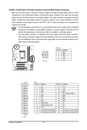
... mainly supplies power to the power connector in the correct orientation. If a power supply is turned off and all the components on the motherboard. Before connecting the power connector, first make sure the power supply is used that can withstand high power consumption be used (500W or ...supply cable into pins under the protective cover when using a 2x12 power supply, remove the protective cover from the main power connector on the motherboard. 1/2) ATX_12V/ATX (2x2 12V Power Connector and 2x12 Main Power Connector) With the use of the power connector, the power supply can ...
... mainly supplies power to the power connector in the correct orientation. If a power supply is turned off and all the components on the motherboard. Before connecting the power connector, first make sure the power supply is used that can withstand high power consumption be used (500W or ...supply cable into pins under the protective cover when using a 2x12 power supply, remove the protective cover from the main power connector on the motherboard. 1/2) ATX_12V/ATX (2x2 12V Power Connector and 2x12 Main Power Connector) With the use of the power connector, the power supply can ...
Manual
Page 23
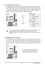
... designated by a stripe of a CPU fan with fan speed control design. The types of the connector and the floppy disk drive cable. The motherboard supports CPU fan speed control, which requires the use of different color. Definition 1 GND 2 +12V / Speed Control 3 Sense 4 Reserve •...; Be sure to connect fan cables to the fan headers to connect a floppy disk drive. 3/4) CPU_FAN/SYS_FAN (Fan Headers) The motherboard has a 4-pin CPU fan header (CPU_FAN) and a 4-pin system fan header (SYS_FAN). For purchasing the optional floppy disk drive cable, please contact ...
... designated by a stripe of a CPU fan with fan speed control design. The types of the connector and the floppy disk drive cable. The motherboard supports CPU fan speed control, which requires the use of different color. Definition 1 GND 2 +12V / Speed Control 3 Sense 4 Reserve •...; Be sure to connect fan cables to the fan headers to connect a floppy disk drive. 3/4) CPU_FAN/SYS_FAN (Fan Headers) The motherboard has a 4-pin CPU fan header (CPU_FAN) and a 4-pin system fan header (SYS_FAN). For purchasing the optional floppy disk drive cable, please contact ...
Manual
Page 27
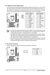
... module connector match the pin assignments of the front and back panel audio connections simultaneously. Pin No. Incorrect connection between the module connector and the motherboard header will be present on each wire instead of a single plug. Definition 1 CD-L 1 2 GND 3 GND 4 CD-R - 27 - 10) F_AUDIO (Front Panel Audio Header) The front... Front Panel Audio: For AC'97 Front Panel Audio: Pin No. You may connect the audio cable that has separated connectors on both of the motherboard header.
... module connector match the pin assignments of the front and back panel audio connections simultaneously. Pin No. Incorrect connection between the module connector and the motherboard header will be present on each wire instead of a single plug. Definition 1 CD-L 1 2 GND 3 GND 4 CD-R - 27 - 10) F_AUDIO (Front Panel Audio Header) The front... Front Panel Audio: For AC'97 Front Panel Audio: Pin No. You may connect the audio cable that has separated connectors on both of the motherboard header.
Manual
Page 28
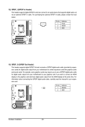
...For example, some graphics cards may require you wish to connect an HDMI display to the graphics card and have digital audio output from your motherboard to an audio device that supports digital audio out via an optional S/PDIF In cable. For purchasing the optional S/PDIF In cable, please...audio cable, carefully read the manual for your graphics card if you to use a S/PDIF digital audio cable for digital audio output from your motherboard to certain expansion cards like graphics cards and sound cards. 12) SPDIF_I (S/PDIF In Header) This header supports digital S/PDIF In and can ...
...For example, some graphics cards may require you wish to connect an HDMI display to the graphics card and have digital audio output from your motherboard to an audio device that supports digital audio out via an optional S/PDIF In cable. For purchasing the optional S/PDIF In cable, please...audio cable, carefully read the manual for your graphics card if you to use a S/PDIF digital audio cable for digital audio output from your motherboard to certain expansion cards like graphics cards and sound cards. 12) SPDIF_I (S/PDIF In Header) This header supports digital S/PDIF In and can ...


