Manual
Page 1
GA-H55M-S2H LGA1156 socket motherboard for Intel® Core™ i7 processor family/ Intel® Core™ i5 processor family/ Intel® Core™ i3 processor family User's Manual Rev. 1001 12ME-H55MS2H-1001R
GA-H55M-S2H LGA1156 socket motherboard for Intel® Core™ i7 processor family/ Intel® Core™ i5 processor family/ Intel® Core™ i3 processor family User's Manual Rev. 1001 12ME-H55MS2H-1001R
Manual
Page 2
Motherboard GA-H55M-S2H Dec. 7, 2009 Motherboard GA-H55M-S2H Dec. 7, 2009
Motherboard GA-H55M-S2H Dec. 7, 2009 Motherboard GA-H55M-S2H Dec. 7, 2009
Manual
Page 3
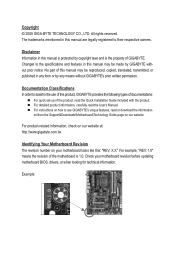
... this manual may be reproduced, copied, translated, transmitted, or published in the use GIGABYTE's unique features, read or download the information on/from the Support&Downloads\Motherboard\Technology Guide page on our website. For detailed product information, carefully read the Quick... The revision number on how to their respective owners. Disclaimer Information in this manual are legally registered to use of GIGABYTE. Check your motherboard looks like this manual is 1.0. Copyright © 2009 GIGA-BYTE TECHNOLOGY CO., LTD. The trademarks mentioned in this : "...
... this manual may be reproduced, copied, translated, transmitted, or published in the use GIGABYTE's unique features, read or download the information on/from the Support&Downloads\Motherboard\Technology Guide page on our website. For detailed product information, carefully read the Quick... The revision number on how to their respective owners. Disclaimer Information in this manual are legally registered to use of GIGABYTE. Check your motherboard looks like this manual is 1.0. Copyright © 2009 GIGA-BYTE TECHNOLOGY CO., LTD. The trademarks mentioned in this : "...
Manual
Page 4
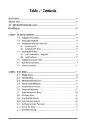
Table of Contents Box Contents...6 Optional Items...6 GA-H55M-S2H Motherboard Layout 7 Block Diagram...8 Chapter 1 Hardware Installation 9 1-1 Installation Precautions 9 1-2 Product Specifications 10 1-3 Installing the CPU and CPU Cooler 13 1-3-1 Installing the CPU 13 1-3-2 Installing the CPU ...
Table of Contents Box Contents...6 Optional Items...6 GA-H55M-S2H Motherboard Layout 7 Block Diagram...8 Chapter 1 Hardware Installation 9 1-1 Installation Precautions 9 1-2 Product Specifications 10 1-3 Installing the CPU and CPU Cooler 13 1-3-1 Installing the CPU 13 1-3-2 Installing the CPU ...
Manual
Page 6
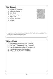
...-1UB030-5*R) 2-port SATA power cable (Part No. 12CF1-2SERPW-0*R) S/PDIF In cable (Part No. 12CR1-1SPDIN-0*R) COM port cable (Part No. 12CF1-1CM001-3*R) - 6 - Box Contents GA-H55M-S2H motherboard Motherboard driver disk User's Manual Quick Installation Guide One IDE cable Two SATA 3Gb/s cables I/O Shield • The box contents above are subject to change without...
...-1UB030-5*R) 2-port SATA power cable (Part No. 12CF1-2SERPW-0*R) S/PDIF In cable (Part No. 12CR1-1SPDIN-0*R) COM port cable (Part No. 12CF1-1CM001-3*R) - 6 - Box Contents GA-H55M-S2H motherboard Motherboard driver disk User's Manual Quick Installation Guide One IDE cable Two SATA 3Gb/s cables I/O Shield • The box contents above are subject to change without...
Manual
Page 7
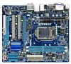
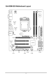
GA-H55M-S2H Motherboard Layout KB_USB ATX_12V VGA_DVI LGA1156 PHASE LED IT8720 HDMI SYS_FAN OPTICAL R_USB USB_LAN CPU_FAN AUDIO F_AUDIO PCIEX16 PCI1 RTL8111D PCI2 SPDIF_O SPDIF_I CODEC PCIEX4 IDE ATX BAT GA-H55M-S2H Intel® H55 JMicron JMB368 M_BIOS B_BIOS CLR_CMOS FDD CD_IN F_USB2 COMA F_USB1 F_PANEL DDR3_1 DDR3_2 SATA2_5 SATA2_2 SATA2_4 SATA2_1 SATA2_3 SATA2_0 - 7 -
GA-H55M-S2H Motherboard Layout KB_USB ATX_12V VGA_DVI LGA1156 PHASE LED IT8720 HDMI SYS_FAN OPTICAL R_USB USB_LAN CPU_FAN AUDIO F_AUDIO PCIEX16 PCI1 RTL8111D PCI2 SPDIF_O SPDIF_I CODEC PCIEX4 IDE ATX BAT GA-H55M-S2H Intel® H55 JMicron JMB368 M_BIOS B_BIOS CLR_CMOS FDD CD_IN F_USB2 COMA F_USB1 F_PANEL DDR3_1 DDR3_2 SATA2_5 SATA2_2 SATA2_4 SATA2_1 SATA2_3 SATA2_0 - 7 -
Manual
Page 9
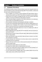
... power during the installation process can become damaged as a result of electrostatic discharge (ESD). Chapter 1 Hardware Installation 1-1 Installation Precautions The motherboard contains numerous delicate electronic circuits and components which can lead to damage to system components as well as physical harm to the user. &#...ESD wrist strap, keep your hands dry and first touch a metal object to eliminate static electricity. • Prior to installing the motherboard, please have it on top of an antistatic pad or within the computer casing. • Do not place the computer system on...
... power during the installation process can become damaged as a result of electrostatic discharge (ESD). Chapter 1 Hardware Installation 1-1 Installation Precautions The motherboard contains numerous delicate electronic circuits and components which can lead to damage to system components as well as physical harm to the user. &#...ESD wrist strap, keep your hands dry and first touch a metal object to eliminate static electricity. • Prior to installing the motherboard, please have it on top of an antistatic pad or within the computer casing. • Do not place the computer system on...
Manual
Page 12
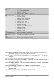
... CPU/system fan speed control function is supported will depend on the CPU/system cooler you install. (Note 8) Available functions in EasyTune may differ by motherboard model.
... CPU/system fan speed control function is supported will depend on the CPU/system cooler you install. (Note 8) Available functions in EasyTune may differ by motherboard model.
Manual
Page 13
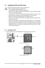
...you may occur. • Set the CPU host frequency in accordance with the CPU specifications. Hardware Installation Locate the alignment keys on the motherboard CPU socket and the notches on the CPU - 13 - The CPU cannot be set the frequency beyond hardware specifications since it does ... Apply an even and thin layer of thermal grease on the computer if the CPU cooler is not recommended that the motherboard supports the CPU. (Go to GIGABYTE's website for the peripherals. 1-3 Installing the CPU and CPU Cooler Read the following guidelines before installing the CPU to prevent...
...you may occur. • Set the CPU host frequency in accordance with the CPU specifications. Hardware Installation Locate the alignment keys on the motherboard CPU socket and the notches on the CPU - 13 - The CPU cannot be set the frequency beyond hardware specifications since it does ... Apply an even and thin layer of thermal grease on the computer if the CPU cooler is not recommended that the motherboard supports the CPU. (Go to GIGABYTE's website for the peripherals. 1-3 Installing the CPU and CPU Cooler Read the following guidelines before installing the CPU to prevent...
Manual
Page 14
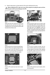
... the CPU into its locked position. Align the CPU pin one marking (triangle) with your finger. Step 5: Push the CPU socket lever back into the motherboard CPU socket. Step 2: Remove the CPU socket cover as well. To protect the CPU socket, always replace the protective socket cover when the CPU is...
... the CPU into its locked position. Align the CPU pin one marking (triangle) with your finger. Step 5: Push the CPU socket lever back into the motherboard CPU socket. Step 2: Remove the CPU socket cover as well. To protect the CPU socket, always replace the protective socket cover when the CPU is...
Manual
Page 15
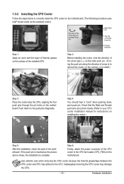
...2: Before installing the cooler, note the direction of the arrow sign on the male push pin. (Turning the push pin along the direction of the motherboard. Step 4: You should hear a "click" when pushing down on the push pins diagonally. Inadequately removing the CPU cooler may adhere to your CPU cooler...Step 1: Apply an even and thin layer of thermal grease on the surface of the CPU cooler to the CPU fan header (CPU_FAN) on the motherboard. Push down each push pin. Step 6: Finally, attach the power connector of the installed CPU. Check that the Male and Female push pins are...
...2: Before installing the cooler, note the direction of the arrow sign on the male push pin. (Turning the push pin along the direction of the motherboard. Step 4: You should hear a "click" when pushing down on the push pins diagonally. Inadequately removing the CPU cooler may adhere to your CPU cooler...Step 1: Apply an even and thin layer of thermal grease on the surface of the CPU cooler to the CPU fan header (CPU_FAN) on the motherboard. Push down each push pin. Step 6: Finally, attach the power connector of the installed CPU. Check that the Male and Female push pins are...
Manual
Page 16
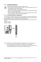
...following: Channel 0: DDR3_1 Channel 1: DDR3_2 DDR3_1 DDR3_2 Due to CPU limitations, read the following guidelines before you are unable to GIGABYTE's website for optimum performance. A memory module can be enabled if only one DDR3 memory module is installed, the BIOS will double..., brand, speed, and chips be used . (Go to insert the memory, switch the direction. 1-4-1 Dual Channel Memory Configuration This motherboard provides two DDR3 memory sockets and supports Dual Channel Technology. If you begin to prevent hardware damage. • Memory modules have a foolproof...
...following: Channel 0: DDR3_1 Channel 1: DDR3_2 DDR3_1 DDR3_2 Due to CPU limitations, read the following guidelines before you are unable to GIGABYTE's website for optimum performance. A memory module can be enabled if only one DDR3 memory module is installed, the BIOS will double..., brand, speed, and chips be used . (Go to insert the memory, switch the direction. 1-4-1 Dual Channel Memory Configuration This motherboard provides two DDR3 memory sockets and supports Dual Channel Technology. If you begin to prevent hardware damage. • Memory modules have a foolproof...
Manual
Page 17
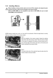
..., make sure to turn off the computer and unplug the power cord from the power outlet to prevent damage to install DDR3 DIMMs on this motherboard. Spread the retaining clips at both ends of the memory module. Place the memory module on the socket. Hardware Installation
..., make sure to turn off the computer and unplug the power cord from the power outlet to prevent damage to install DDR3 DIMMs on this motherboard. Spread the retaining clips at both ends of the memory module. Place the memory module on the socket. Hardware Installation
Manual
Page 18
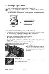
... correctly install your computer. PCI Express x16 Slot (PCIEX16/PCIEX4) PCI Slot Follow the steps below to install an expansion card: • Make sure the motherboard supports the expansion card. Make sure the metal contacts on the top edge of the PCI Express slot to make any required BIOS changes for...
... correctly install your computer. PCI Express x16 Slot (PCIEX16/PCIEX4) PCI Slot Follow the steps below to install an expansion card: • Make sure the motherboard supports the expansion card. Make sure the metal contacts on the top edge of the PCI Express slot to make any required BIOS changes for...
Manual
Page 20
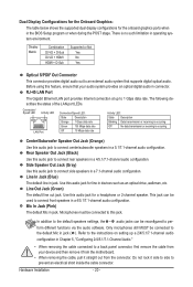
...: The table below shows the supported dual display configurations for the onboard graphics ports when in jack ( ). Do not rock it straight out from the motherboard. • When removing the cable, pull it side to side to this audio jack for a headphone or 2-channel speaker.
...: The table below shows the supported dual display configurations for the onboard graphics ports when in jack ( ). Do not rock it straight out from the motherboard. • When removing the cable, pull it side to side to this audio jack for a headphone or 2-channel speaker.
Manual
Page 21
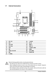
...) F_AUDIO 11) CD_IN 12) SPDIF_I 13) SPDIF_O 14) F_USB1/F_USB2 15) COMA 16) CLR_CMOS 17) PHASE LED Read the following guidelines before turning on the motherboard. - 21 - Hardware Installation
...) F_AUDIO 11) CD_IN 12) SPDIF_I 13) SPDIF_O 14) F_USB1/F_USB2 15) COMA 16) CLR_CMOS 17) PHASE LED Read the following guidelines before turning on the motherboard. - 21 - Hardware Installation
Manual
Page 22
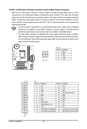
... power supply cable into pins under the protective cover when using a 2x12 power supply, remove the protective cover from the main power connector on the motherboard. Before connecting the power connector, first make sure the power supply is turned off and all the components on the...
... power supply cable into pins under the protective cover when using a 2x12 power supply, remove the protective cover from the main power connector on the motherboard. Before connecting the power connector, first make sure the power supply is turned off and all the components on the...
Manual
Page 23
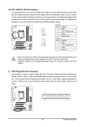
... Speed Control 3 Sense 4 Reserve • Be sure to connect fan cables to the fan headers to connect it is the ground wire). The motherboard supports CPU fan speed control, which requires the use of the connector and the floppy disk drive cable. Definition 1 GND 2 +12V / Speed ...Control 3 Sense 4 Speed Control SYS_FAN: Pin No. 3/4) CPU_FAN/SYS_FAN (Fan Headers) The motherboard has a 4-pin CPU fan header (CPU_FAN) and a 4-pin system fan header (SYS_FAN). Most fan headers possess a foolproof insertion design. For optimum heat...
... Speed Control 3 Sense 4 Reserve • Be sure to connect fan cables to the fan headers to connect it is the ground wire). The motherboard supports CPU fan speed control, which requires the use of the connector and the floppy disk drive cable. Definition 1 GND 2 +12V / Speed ...Control 3 Sense 4 Speed Control SYS_FAN: Pin No. 3/4) CPU_FAN/SYS_FAN (Fan Headers) The motherboard has a 4-pin CPU fan header (CPU_FAN) and a 4-pin system fan header (SYS_FAN). Most fan headers possess a foolproof insertion design. For optimum heat...
Manual
Page 27
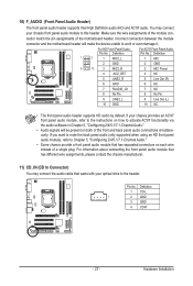
... "Configuring 2/4/5.1/7.1-Channel Audio." • Some chassis provide a front panel audio module that has separated connectors on both of the motherboard header. Make sure the wire assignments of the module connector match the pin assignments of the front and back panel audio connections ...simultaneously. Pin No. Definition 1 CD-L 1 2 GND 3 GND 4 CD-R - 27 - Incorrect connection between the module connector and the motherboard header will be present on each wire instead of a single plug. 10) F_AUDIO (Front Panel Audio Header) The front panel audio header supports...
... "Configuring 2/4/5.1/7.1-Channel Audio." • Some chassis provide a front panel audio module that has separated connectors on both of the motherboard header. Make sure the wire assignments of the module connector match the pin assignments of the front and back panel audio connections ...simultaneously. Pin No. Definition 1 CD-L 1 2 GND 3 GND 4 CD-R - 27 - Incorrect connection between the module connector and the motherboard header will be present on each wire instead of a single plug. 10) F_AUDIO (Front Panel Audio Header) The front panel audio header supports...
Manual
Page 28
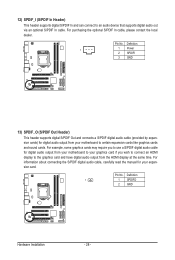
... S/PDIF Out and connects a S/PDIF digital audio cable (provided by expansion cards) for digital audio output from your motherboard to your graphics card if you to use a S/PDIF digital audio cable for your motherboard to an audio device that supports digital audio out via an optional S/PDIF In cable. Pin No. Definition...
... S/PDIF Out and connects a S/PDIF digital audio cable (provided by expansion cards) for digital audio output from your motherboard to your graphics card if you to use a S/PDIF digital audio cable for your motherboard to an audio device that supports digital audio out via an optional S/PDIF In cable. Pin No. Definition...


