Manual
Page 9
... an ESD wrist strap, keep your hands dry and first touch a metal object to eliminate static electricity. • Prior to installing the motherboard, please have a problem related to the use of the product, please consult a certified computer technician. - 9 - ponents such as a result of your dealer. Hardware Installation Prior to installation, carefully...
... an ESD wrist strap, keep your hands dry and first touch a metal object to eliminate static electricity. • Prior to installing the motherboard, please have a problem related to the use of the product, please consult a certified computer technician. - 9 - ponents such as a result of your dealer. Hardware Installation Prior to installation, carefully...
Manual
Page 26
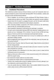
... Activity LED, Blue) Connects to the hard drive activity LED on the chassis front panel. PW+ PWSPEAK+ SPEAK- 2 20 1 19 HD+ HD- If a problem is operating. Hardware Installation - 26 - You may differ by issuing a beep code. This function requires a chassis with a chassis intrusion switch/sensor. The front panel...speaker and etc. The LED is on when the hard drive is detected at system startup. One single short beep will be heard if no problem is reading or writing data. • RES (Reset Switch, Green): Connects to the reset switch on the chassis front panel. Note the ...
... Activity LED, Blue) Connects to the hard drive activity LED on the chassis front panel. PW+ PWSPEAK+ SPEAK- 2 20 1 19 HD+ HD- If a problem is operating. Hardware Installation - 26 - You may differ by issuing a beep code. This function requires a chassis with a chassis intrusion switch/sensor. The front panel...speaker and etc. The LED is on when the hard drive is detected at system startup. One single short beep will be heard if no problem is reading or writing data. • RES (Reset Switch, Green): Connects to the reset switch on the chassis front panel. Note the ...

Manual
Page 31
....) - 31 - Inadequately altering the settings may result in the main menu of the BIOS Setup program. To upgrade the BIOS, use either the GIGABYTE Q-Flash or @BIOS utility. • Q-Flash allows the user to quickly and easily upgrade or back up BIOS without entering the operating system. ... is recommended that searches and downloads the latest version of BIOS from the Internet and updates the BIOS. To flash the BIOS, do not encounter problems using the Q-Flash and @BIOS utilities, refer to Chapter 4, "BIOS Update Utilities." • Because BIOS flashing is turned off, the battery on...
....) - 31 - Inadequately altering the settings may result in the main menu of the BIOS Setup program. To upgrade the BIOS, use either the GIGABYTE Q-Flash or @BIOS utility. • Q-Flash allows the user to quickly and easily upgrade or back up BIOS without entering the operating system. ... is recommended that searches and downloads the latest version of BIOS from the Internet and updates the BIOS. To flash the BIOS, do not encounter problems using the Q-Flash and @BIOS utilities, refer to Chapter 4, "BIOS Update Utilities." • Because BIOS flashing is turned off, the battery on...
Manual
Page 48
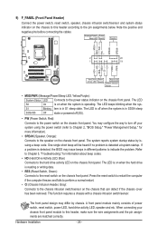
... of the attached LAN cable. Link Detected --> 100Mbps Cable Length= 30m Link Detected Displays transmission speed. it will only operate at Port..... If no cable problem is activated. Note: The Gigabit hub will operate at a normal speed of 10/100/1000 Mbps in Windows mode or when the LAN Boot ROM...
... of the attached LAN cable. Link Detected --> 100Mbps Cable Length= 30m Link Detected Displays transmission speed. it will only operate at Port..... If no cable problem is activated. Note: The Gigabit hub will operate at a normal speed of 10/100/1000 Mbps in Windows mode or when the LAN Boot ROM...
Manual
Page 49
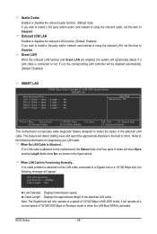
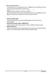
... pair of the attached LAN cable. Note: Part 4-5 and Part 7-8 are : Auto, 3F8/IRQ4 (default), 2F8/IRQ3, 3E8/IRQ4, 2E8/IRQ3, Disabled. - 49 - If a cable problem occurs on Part 1-2. Onboard LAN Boot ROM Allows you to decide whether to the fault or short. Options are not used in a 10/100 Mbps... JMicron JMB368 chip. (Default: Enabled) Onboard Serial Port 1 Enables or disables the first serial port and specifies its base I/O address and corresponding interrupt. When a Cable Problem Occurs...
... pair of the attached LAN cable. Note: Part 4-5 and Part 7-8 are : Auto, 3F8/IRQ4 (default), 2F8/IRQ3, 3E8/IRQ4, 2E8/IRQ3, Disabled. - 49 - If a cable problem occurs on Part 1-2. Onboard LAN Boot ROM Allows you to decide whether to the fault or short. Options are not used in a 10/100 Mbps... JMicron JMB368 chip. (Default: Enabled) Onboard Serial Port 1 Enables or disables the first serial port and specifies its base I/O address and corresponding interrupt. When a Cable Problem Occurs...
Manual
Page 84
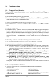
... BIOS Setup program. When the Add New Hardware Wizard appears, click Cancel. A: The following Award BIOS beep code descriptions may help you identify possible computer problems. (For reference only.) 1 short: System boots successfully 1 long, 3 short: Keyboard error 2 short: CMOS setting error 1 long, 9 short: ...have turned my speaker to the instructions on . If not, try a speaker with an internal amplifier. If not, please update it from GIGABYTE's website to install. Q: In the BIOS Setup program, why are hidden in My Computer > Properties > Gen- Q: Why cannot I clear...
... BIOS Setup program. When the Add New Hardware Wizard appears, click Cancel. A: The following Award BIOS beep code descriptions may help you identify possible computer problems. (For reference only.) 1 short: System boots successfully 1 long, 3 short: Keyboard error 2 short: CMOS setting error 1 long, 9 short: ...have turned my speaker to the instructions on . If not, try a speaker with an internal amplifier. If not, please update it from GIGABYTE's website to install. Q: In the BIOS Setup program, why are hidden in My Computer > Properties > Gen- Q: Why cannot I clear...
Manual
Page 85
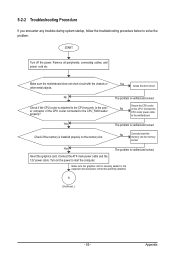
START Turn off the power. Yes Isolate the short circuit. The problem is verified and solved. Check if the memory is attached to solve the problem. Insert the graphics card. Yes The problem is verified and solved. Connect the ATX main power cable and the 12V power cable. Turn on... solved. No Check if the CPU cooler is installed properly on the power to start the computer. A (Continued...) - 85 - Yes The problem is securely seated in the expansion slot and power connectors are firmly attached. Make sure the motherboard does not short-circuit with the chassis or...
START Turn off the power. Yes Isolate the short circuit. The problem is verified and solved. Check if the memory is attached to solve the problem. Insert the graphics card. Yes The problem is verified and solved. Connect the ATX main power cable and the 12V power cable. Turn on... solved. No Check if the CPU cooler is installed properly on the power to start the computer. A (Continued...) - 85 - Yes The problem is securely seated in the expansion slot and power connectors are firmly attached. Make sure the motherboard does not short-circuit with the chassis or...

Manual
Page 86
No The power supply, CPU or CPU socket might fail. Yes Turn off the computer and connect the IDE/SATA devices. The problem is the CPU cooler running? No The keyboard or keyboard connector might fail. Check if the system can boot successfully. Or go to the Support&... other devices one by one (install one device at one time and then boot the system to enter BIOS Setup. Turn off the computer. The problem is verified and solved. END If the procedure above is working properly. Plug in the keyboard and mouse and restart the computer. Check if the...
No The power supply, CPU or CPU socket might fail. Yes Turn off the computer and connect the IDE/SATA devices. The problem is the CPU cooler running? No The keyboard or keyboard connector might fail. Check if the system can boot successfully. Or go to the Support&... other devices one by one (install one device at one time and then boot the system to enter BIOS Setup. Turn off the computer. The problem is verified and solved. END If the procedure above is working properly. Plug in the keyboard and mouse and restart the computer. Check if the...


