Manual
Page 3
.... For instructions on how to assist in the use GIGABYTE's unique features, read the User's Manual. For detailed product information, carefully read or download the information on/from the Support&Downloads\Motherboard\Technology Guide page on your motherboard revision before updating motherboard BIOS, drivers, or when looking for technical information. Documentation Classifications In order to use of this product, GIGABYTE provides the following types of documentations: For quick set-up...
.... For instructions on how to assist in the use GIGABYTE's unique features, read the User's Manual. For detailed product information, carefully read or download the information on/from the Support&Downloads\Motherboard\Technology Guide page on your motherboard revision before updating motherboard BIOS, drivers, or when looking for technical information. Documentation Classifications In order to use of this product, GIGABYTE provides the following types of documentations: For quick set-up...
Manual
Page 4
...of Contents Box Contents...6 Optional Items...6 GA-H55M-S2H Motherboard Layout 7 Block Diagram...8 Chapter 1 Hardware Installation 9 1-1 Installation Precautions 9 1-2 Product Specifications 10 1-3 Installing the CPU and CPU Cooler 13 1-3-1 Installing the CPU 13 1-3-2 Installing the CPU Cooler 15 1-4 Installing the Memory 16 1-4-1 Dual Channel Memory Configuration 16 1-4-2 Installing a Memory 17 1-5 Installing an Expansion Card 18 1-6 Back Panel Connectors 19 1-7 Internal Connectors 21 Chapter 2 BIOS Setup 31 2-1 Startup Screen 32 2-2 The Main Menu 33 2-3 MB Intelligent Tweaker...
...of Contents Box Contents...6 Optional Items...6 GA-H55M-S2H Motherboard Layout 7 Block Diagram...8 Chapter 1 Hardware Installation 9 1-1 Installation Precautions 9 1-2 Product Specifications 10 1-3 Installing the CPU and CPU Cooler 13 1-3-1 Installing the CPU 13 1-3-2 Installing the CPU Cooler 15 1-4 Installing the Memory 16 1-4-1 Dual Channel Memory Configuration 16 1-4-2 Installing a Memory 17 1-5 Installing an Expansion Card 18 1-6 Back Panel Connectors 19 1-7 Internal Connectors 21 Chapter 2 BIOS Setup 31 2-1 Startup Screen 32 2-2 The Main Menu 33 2-3 MB Intelligent Tweaker...
Manual
Page 16
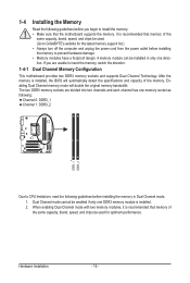
... to GIGABYTE's website for optimum performance. Dual Channel mode cannot be used for the latest memory support list.) • Always turn off the computer and unplug the power cord from the power outlet before installing the memory to insert the memory, switch the direction. 1-4-1 Dual Channel Memory Configuration This motherboard provides two DDR3 memory sockets and supports Dual Channel Technology. Hardware Installation - 16 - Enabling Dual Channel memory mode will automatically detect the specifications and capacity of the same capacity, brand, speed, and chips be enabled if...
... to GIGABYTE's website for optimum performance. Dual Channel mode cannot be used for the latest memory support list.) • Always turn off the computer and unplug the power cord from the power outlet before installing the memory to insert the memory, switch the direction. 1-4-1 Dual Channel Memory Configuration This motherboard provides two DDR3 memory sockets and supports Dual Channel Technology. Hardware Installation - 16 - Enabling Dual Channel memory mode will automatically detect the specifications and capacity of the same capacity, brand, speed, and chips be enabled if...
Manual
Page 18
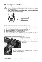
... card. Turn on the top edge of the PCI Express slot to make any required BIOS changes for your expansion card in the slot. 3. If necessary, go to BIOS Setup to release the card and then pull the card straight up from the slot. Remove the metal slot cover from the power outlet before you begin to correctly install your expansion card(s). 7. Secure the card's metal bracket to the chassis back panel...
... card. Turn on the top edge of the PCI Express slot to make any required BIOS changes for your expansion card in the slot. 3. If necessary, go to BIOS Setup to release the card and then pull the card straight up from the slot. Remove the metal slot cover from the power outlet before you begin to correctly install your expansion card(s). 7. Secure the card's metal bracket to the chassis back panel...
Manual
Page 19
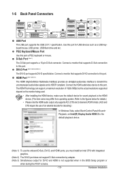
... resolutions supported depend on the monitor being used. • After installing the HDMI device, make sure the default device for DVI-D and HDMI is not supported when in the BIOS Setup program or when during the POST screens. - 19 - Connect the HDMI audio/video device to this port. Connect a monitor that supports DVI-D connection to this port for USB devices such as a USB keyboard/mouse, USB printer, USB flash drive and etc. Connect a monitor that supports D-Sub connection to transmit the uncompressed audio/video signals and is the HDMI device. (The...
... resolutions supported depend on the monitor being used. • After installing the HDMI device, make sure the default device for DVI-D and HDMI is not supported when in the BIOS Setup program or when during the POST screens. - 19 - Connect the HDMI audio/video device to this port. Connect a monitor that supports DVI-D connection to this port for USB devices such as a USB keyboard/mouse, USB printer, USB flash drive and etc. Connect a monitor that supports D-Sub connection to transmit the uncompressed audio/video signals and is the HDMI device. (The...
Manual
Page 20
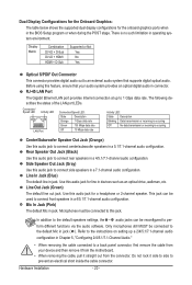
... connect front speakers in devices such as an optical drive, walkman, etc. Hardware Installation - 20 - Display Matrix Combination Supported or Not DVI-D + D-Sub Yes DVI-D + HDMI No HDMI + D-Sub Yes Optical S/PDIF Out Connector This connector provides digital audio out to prevent an electrical short inside the cable connector. Rear Speaker Out Jack (Black) Use this jack. Refer to the instructions on setting up to connect center/subwoofer speakers in jack. Dual Display Configurations...
... connect front speakers in devices such as an optical drive, walkman, etc. Hardware Installation - 20 - Display Matrix Combination Supported or Not DVI-D + D-Sub Yes DVI-D + HDMI No HDMI + D-Sub Yes Optical S/PDIF Out Connector This connector provides digital audio out to prevent an electrical short inside the cable connector. Rear Speaker Out Jack (Black) Use this jack. Refer to the instructions on setting up to connect center/subwoofer speakers in jack. Dual Display Configurations...
Manual
Page 30
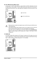
... lighted LEDs indicates the CPU loading. To enable the Phase LED display function, please first enable Dynamic Energy Saver™ 2. Failure to do so may cause damage to the motherboard. • After system restart, go to BIOS Setup to load factory defaults (select Load Optimized Defaults) or manually configure the BIOS settings (refer to touch the two pins for a few seconds. 16) CLR_CMOS (Clearing CMOS Jumper) Use this jumper to factory defaults. Hardware Installation - 30 - date information and BIOS configurations...
... lighted LEDs indicates the CPU loading. To enable the Phase LED display function, please first enable Dynamic Energy Saver™ 2. Failure to do so may cause damage to the motherboard. • After system restart, go to BIOS Setup to load factory defaults (select Load Optimized Defaults) or manually configure the BIOS settings (refer to touch the two pins for a few seconds. 16) CLR_CMOS (Clearing CMOS Jumper) Use this jumper to factory defaults. Hardware Installation - 30 - date information and BIOS configurations...
Manual
Page 34
... CPU, memory, etc. Standard CMOS Features Use this menu to configure the system time and date, hard drive types, floppy disk drive types, and the type of errors that stop the system boot, etc. Advanced BIOS Features Use this menu to configure the device boot order, advanced features available on the CPU, and the primary display adapter. Integrated Peripherals Use this menu to configure all peripheral devices, such as IDE, SATA, USB, integrated audio, and integrated LAN, etc. Power Management Setup Use...
... CPU, memory, etc. Standard CMOS Features Use this menu to configure the system time and date, hard drive types, floppy disk drive types, and the type of errors that stop the system boot, etc. Advanced BIOS Features Use this menu to configure the device boot order, advanced features available on the CPU, and the primary display adapter. Integrated Peripherals Use this menu to configure all peripheral devices, such as IDE, SATA, USB, integrated audio, and integrated LAN, etc. Power Management Setup Use...
Manual
Page 37
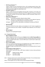
... Base Clock(BCLK) Control option is highly recommended that supports this feature. BIOS Setup Disabled Disables this setting. (Default: Auto) CPU EIST Function (Note 1) Enables or disables Enhanced Intel SpeedStep Technology (EIST). Enabled will be emitted to lower CPU performance to manually set in accordance with unlocked clock ratio is dependent on CPU loading, Intel EIST technology can dynamically and effectively lower the CPU voltage and core frequency to 600 MHz. CPU Thermal Monitor (Note 1) Enables or disables Intel CPU Thermal Monitor function, a CPU overheating...
... Base Clock(BCLK) Control option is highly recommended that supports this feature. BIOS Setup Disabled Disables this setting. (Default: Auto) CPU EIST Function (Note 1) Enables or disables Enhanced Intel SpeedStep Technology (EIST). Enabled will be emitted to lower CPU performance to manually set in accordance with unlocked clock ratio is dependent on CPU loading, Intel EIST technology can dynamically and effectively lower the CPU voltage and core frequency to 600 MHz. CPU Thermal Monitor (Note 1) Enables or disables Intel CPU Thermal Monitor function, a CPU overheating...
Manual
Page 40
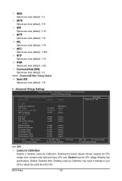
... Auto (default), 1~10 tRFC Options are : Auto (default), 1~15. Enabling this feature adjusts Vdroop, keeping the CPU voltage more constant under light and heavy CPU load. tWR Options are : Auto (default), 1~255. tRTP Options are : Auto (default), 1~31. tWTR Options are : Auto (default), 1~15. tFAW Options are : Auto (default), 1~31. Advanced Voltage Settings CMOS Setup Utility-Copyright (C) 1984-2009 Award Software Advanced Voltage Settings ****** Mother Board Voltage Control ****** Voltage Types Normal Current >>> CPU Load-Line Calibration [Disabled] CPU...
... Auto (default), 1~10 tRFC Options are : Auto (default), 1~15. Enabling this feature adjusts Vdroop, keeping the CPU voltage more constant under light and heavy CPU load. tWR Options are : Auto (default), 1~255. tRTP Options are : Auto (default), 1~31. tWTR Options are : Auto (default), 1~15. tFAW Options are : Auto (default), 1~31. Advanced Voltage Settings CMOS Setup Utility-Copyright (C) 1984-2009 Award Software Advanced Voltage Settings ****** Mother Board Voltage Control ****** Voltage Types Normal Current >>> CPU Load-Line Calibration [Disabled] CPU...
Manual
Page 42
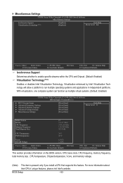
...: Save F6: Fail-Safe Defaults ESC: Exit F1: General Help F7: Optimized Defaults This section provides information on the BIOS version, CPU base clock, CPU frequency, memory frequency, total memory size , CPU temperature, Chipset temperature, Vcore, and memory voltage. (Note) This item is present only if you install a CPU that supports this feature. Miscellaneous Settings CMOS Setup Utility-Copyright (C) 1984-2009 Award Software Miscellaneous Settings Isochronous Support Virtualization Technology (Note) [Enabled] [Enabled] Item Help Menu Level Move...
...: Save F6: Fail-Safe Defaults ESC: Exit F1: General Help F7: Optimized Defaults This section provides information on the BIOS version, CPU base clock, CPU frequency, memory frequency, total memory size , CPU temperature, Chipset temperature, Vcore, and memory voltage. (Note) This item is present only if you install a CPU that supports this feature. Miscellaneous Settings CMOS Setup Utility-Copyright (C) 1984-2009 Award Software Miscellaneous Settings Isochronous Support Virtualization Technology (Note) [Enabled] [Enabled] Item Help Menu Level Move...
Manual
Page 45
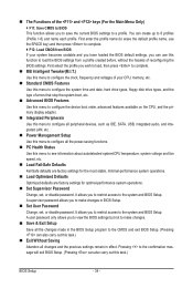
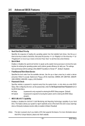
...Smart 6™. (Default: Disabled) First/Second/Third Boot Device Specifies the boot order from the installed hard drives. Options are: Floppy, LS120, Hard Disk, CDROM, ZIP, USB-FDD, USB-ZIP, USB-CDROM, USB-HDD, Legacy LAN, Disabled. Capability Limit CPUID Max. HDD S.M.A.R.T. Quick Boot Enables or disables the quick boot function to speed up the system boot-up process to shorten the waiting time for entering the operating system and to HDD Init Display First Onboard VGA On-Chip Frame Buffer Size [Press Enter] [Disabled] [Hard Disk] [CDROM] [Floppy] [Setup] [Disabled...
...Smart 6™. (Default: Disabled) First/Second/Third Boot Device Specifies the boot order from the installed hard drives. Options are: Floppy, LS120, Hard Disk, CDROM, ZIP, USB-FDD, USB-ZIP, USB-CDROM, USB-HDD, Legacy LAN, Disabled. Capability Limit CPUID Max. HDD S.M.A.R.T. Quick Boot Enables or disables the quick boot function to speed up the system boot-up process to shorten the waiting time for entering the operating system and to HDD Init Display First Onboard VGA On-Chip Frame Buffer Size [Press Enter] [Disabled] [Hard Disk] [CDROM] [Floppy] [Setup] [Disabled...
Manual
Page 46
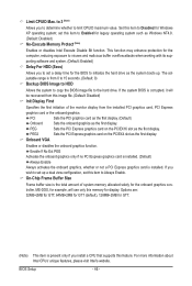
... wish to set this image file. (Default: Disabled) Init Display First Specifies the first initiation of system memory allocated solely for the BIOS to the hard drive. If you to determine whether to Always Enable. BIOS Setup - 46 - porting software and system. (Default: Enabled) Delay For HDD (Secs) Allows you install a CPU that supports this item to Disabled for display. Onboard VGA Enables or disables the onboard graphics function. If the system BIOS is corrupted, it will use only this...
... wish to set this image file. (Default: Disabled) Init Display First Specifies the first initiation of system memory allocated solely for the BIOS to the hard drive. If you to determine whether to Always Enable. BIOS Setup - 46 - porting software and system. (Default: Enabled) Delay For HDD (Secs) Allows you install a CPU that supports this item to Disabled for display. Onboard VGA Enables or disables the onboard graphics function. If the system BIOS is corrupted, it will use only this...
Manual
Page 47
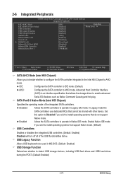
.... Set this option to Disabled if you wish to install operating systems that cannot be used in Legacy IDE mode. In Legacy mode the SATA controllers use dedicated IRQs that do not support Native mode. 2-6 Integrated Peripherals CMOS Setup Utility-Copyright (C) 1984-2009 Award Software Integrated Peripherals SATA AHCI Mode SATA Port0-3 Native Mode USB Controllers USB Legacy Function USB Storage Function Azalia Codec Onboard H/W LAN Green LAN } SMART LAN Onboard LAN Boot ROM Onboard IDE Controller Onboard Serial Port 1 [IDE...
.... Set this option to Disabled if you wish to install operating systems that cannot be used in Legacy IDE mode. In Legacy mode the SATA controllers use dedicated IRQs that do not support Native mode. 2-6 Integrated Peripherals CMOS Setup Utility-Copyright (C) 1984-2009 Award Software Integrated Peripherals SATA AHCI Mode SATA Port0-3 Native Mode USB Controllers USB Legacy Function USB Storage Function Azalia Codec Onboard H/W LAN Green LAN } SMART LAN Onboard LAN Boot ROM Onboard IDE Controller Onboard Serial Port 1 [IDE...
Manual
Page 48
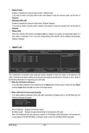
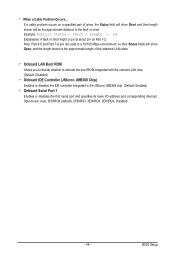
... corresponding LAN controller will appear: Start detecting at Port..... Azalia Codec Enables or disables the onboard audio function. (Default: Auto) If you wish to install a 3rd party add-in the figure above. When LAN Cable Is Functioning Normally... Note: The Gigabit hub will operate at a speed of 10/100 Mbps in audio card instead of 10/100/1000 Mbps in Windows mode or when the LAN Boot ROM is connected or not...
... corresponding LAN controller will appear: Start detecting at Port..... Azalia Codec Enables or disables the onboard audio function. (Default: Auto) If you wish to install a 3rd party add-in the figure above. When LAN Cable Is Functioning Normally... Note: The Gigabit hub will operate at a speed of 10/100 Mbps in audio card instead of 10/100/1000 Mbps in Windows mode or when the LAN Boot ROM is connected or not...
Manual
Page 49
... short. If a cable problem occurs on Part 1-2. BIOS Setup Options are not used in a 10/100 Mbps environment, so their Status fields will show Open, and the length shown is the approximate length of wires, the Status field will show Short and then length shown will be the approximate distance to activate the boot ROM integrated with the onboard LAN chip. (Default: Disabled) Onboard IDE Controller (JMicron JMB368 Chip) Enables or disables the IDE controller...
... short. If a cable problem occurs on Part 1-2. BIOS Setup Options are not used in a 10/100 Mbps environment, so their Status fields will show Open, and the length shown is the approximate length of wires, the Status field will show Short and then length shown will be the approximate distance to activate the boot ROM integrated with the onboard LAN chip. (Default: Disabled) Onboard IDE Controller (JMicron JMB368 Chip) Enables or disables the IDE controller...
Manual
Page 50
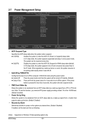
... By Keyboard x KB Power ON Password AC Back Function EuP Support [S3(STR)] [Instant-Off] [Enabled] [Enabled] [Disabled] Everyday 0 : 0 : 0 [Enabled] [32-bit mode] [Disabled] [Disabled] Enter [Soft-Off] [Disabled] Item Help Menu Level Move Enter: Select F5: Previous Values +/-/PU/PD: Value F10: Save F6: Fail-Safe Defaults ESC: Exit F1: General Help F7: Optimized Defaults ACPI Suspend Type Specifies the ACPI sleep state when the system enters suspend. 2-7 Power Management Setup CMOS Setup Utility-Copyright (C) 1984-2009 Award Software Power...
... By Keyboard x KB Power ON Password AC Back Function EuP Support [S3(STR)] [Instant-Off] [Enabled] [Enabled] [Disabled] Everyday 0 : 0 : 0 [Enabled] [32-bit mode] [Disabled] [Disabled] Enter [Soft-Off] [Disabled] Item Help Menu Level Move Enter: Select F5: Previous Values +/-/PU/PD: Value F10: Save F6: Fail-Safe Defaults ESC: Exit F1: General Help F7: Optimized Defaults ACPI Suspend Type Specifies the ACPI sleep state when the system enters suspend. 2-7 Power Management Setup CMOS Setup Utility-Copyright (C) 1984-2009 Award Software Power...

Manual
Page 64
... BIOS Setup. However, if the BIOS update file is potentially risky, please do it with the Q-Flash Utility A. What is Q-Flash™? H55M-S2H E2 . . . . : BIOS Setup : XpressRecovery2 : Boot Menu : Qflash 11/16/2009-H55-7A89TG0FC-00 Because BIOS flashing is saved to a hard drive in RAID/AHCI mode or a hard drive attached to an independent IDE/SATA controller, use the key during the POST or pressing the key in the BIOS, the Q-Flash tool frees you to -use FAT32/16/12 file system. 3. GIGABYTE Q-Flash and @BIOS...
... BIOS Setup. However, if the BIOS update file is potentially risky, please do it with the Q-Flash Utility A. What is Q-Flash™? H55M-S2H E2 . . . . : BIOS Setup : XpressRecovery2 : Boot Menu : Qflash 11/16/2009-H55-7A89TG0FC-00 Because BIOS flashing is saved to a hard drive in RAID/AHCI mode or a hard drive attached to an independent IDE/SATA controller, use the key during the POST or pressing the key in the BIOS, the Q-Flash tool frees you to -use FAT32/16/12 file system. 3. GIGABYTE Q-Flash and @BIOS...
Manual
Page 65
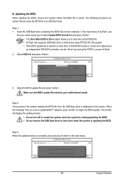
... supports USB flash drive or hard drives using FAT32/16/12 file system. • If the BIOS update file is saved to a hard drive in RAID/AHCI mode or a hard drive attached to an independent IDE/SATA controller, use the up or down arrow key to select Update BIOS from Drive Please SparevsesBaInOySketoy Dtoricvoentinue Enter : Run hi:Move ESC:Reset F10:Power Off - 65 - Select HDD 0-0 and press . Step 2: The process of Q-Flash, use the key during the POST to Drive Enter : Run hi:Move Total size...
... supports USB flash drive or hard drives using FAT32/16/12 file system. • If the BIOS update file is saved to a hard drive in RAID/AHCI mode or a hard drive attached to an independent IDE/SATA controller, use the up or down arrow key to select Update BIOS from Drive Please SparevsesBaInOySketoy Dtoricvoentinue Enter : Run hi:Move ESC:Reset F10:Power Off - 65 - Select HDD 0-0 and press . Step 2: The process of Q-Flash, use the key during the POST to Drive Enter : Run hi:Move Total size...
Manual
Page 84
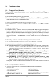
...this device. (If not, skip this step.) Step 3: Then go to enter BIOS Setup during the POST mean? A: The following Award BIOS beep code descriptions may help you identify possible computer problems. (For reference only.) 1 short: System boots successfully 1 long, 3 short: Keyboard error 2 short: CMOS setting error 1 long, 9 short: BIOS ROM error 1 long, 1 short: Memory or motherboard error Continuous long beeps: Graphics card not inserted properly 1 long, 2 short: Monitor or graphics card error Continuous short beeps: Power error Appendix - 84 - Press to the Support&Downloads...
...this device. (If not, skip this step.) Step 3: Then go to enter BIOS Setup during the POST mean? A: The following Award BIOS beep code descriptions may help you identify possible computer problems. (For reference only.) 1 short: System boots successfully 1 long, 3 short: Keyboard error 2 short: CMOS setting error 1 long, 9 short: BIOS ROM error 1 long, 1 short: Memory or motherboard error Continuous long beeps: Graphics card not inserted properly 1 long, 2 short: Monitor or graphics card error Continuous short beeps: Power error Appendix - 84 - Press to the Support&Downloads...


