Manual
Page 1
GA-H55M-S2H LGA1156 socket motherboard for Intel® Core™ i7 processor family/ Intel® Core™ i5 processor family/ Intel® Core™ i3 processor family User's Manual Rev. 1001 12ME-H55MS2H-1001R
GA-H55M-S2H LGA1156 socket motherboard for Intel® Core™ i7 processor family/ Intel® Core™ i5 processor family/ Intel® Core™ i3 processor family User's Manual Rev. 1001 12ME-H55MS2H-1001R
Manual
Page 3
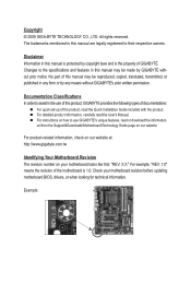
... your motherboard looks like this: "REV: X.X." The trademarks mentioned in this manual may be reproduced, copied, translated, transmitted, or published in this manual may be made by GIGABYTE without GIGABYTE's prior written permission. For product-related information, check on our website at... means without prior notice. No part of GIGABYTE. Documentation Classifications In order to assist in this manual are legally registered to the specifications and features in the use GIGABYTE's unique features, read the User's Manual. Example: Copyright © 2009 GIGA-BYTE...
... your motherboard looks like this: "REV: X.X." The trademarks mentioned in this manual may be reproduced, copied, translated, transmitted, or published in this manual may be made by GIGABYTE without GIGABYTE's prior written permission. For product-related information, check on our website at... means without prior notice. No part of GIGABYTE. Documentation Classifications In order to assist in this manual are legally registered to the specifications and features in the use GIGABYTE's unique features, read the User's Manual. Example: Copyright © 2009 GIGA-BYTE...
Manual
Page 5
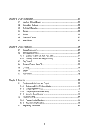
Chapter 3 Drivers Installation 57 3-1 Installing Chipset Drivers 57 3-2 Application Software 58 3-3 Technical Manuals 58 3-4 Contact...59 3-5 System...59 3-6 Download Center 60 3-7 New Utilities...60 Chapter 4 Unique Features 61 4-1 Xpress Recovery2 61 4-2 BIOS Update Utilities 64 4-2-1 Updating the BIOS ...
Chapter 3 Drivers Installation 57 3-1 Installing Chipset Drivers 57 3-2 Application Software 58 3-3 Technical Manuals 58 3-4 Contact...59 3-5 System...59 3-6 Download Center 60 3-7 New Utilities...60 Chapter 4 Unique Features 61 4-1 Xpress Recovery2 61 4-2 BIOS Update Utilities 64 4-2-1 Updating the BIOS ...
Manual
Page 6
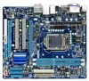
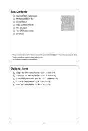
... In cable (Part No. 12CR1-1SPDIN-0*R) COM port cable (Part No. 12CF1-1CM001-3*R) - 6 - The box contents are for reference only. Box Contents GA-H55M-S2H motherboard Motherboard driver disk User's Manual Quick Installation Guide One IDE cable Two SATA 3Gb/s cables I/O Shield • The box contents above are subject to change without notice. •...
... In cable (Part No. 12CR1-1SPDIN-0*R) COM port cable (Part No. 12CF1-1CM001-3*R) - 6 - The box contents are for reference only. Box Contents GA-H55M-S2H motherboard Motherboard driver disk User's Manual Quick Installation Guide One IDE cable Two SATA 3Gb/s cables I/O Shield • The box contents above are subject to change without notice. •...
Manual
Page 9
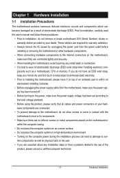
... the product, please verify that all cables and power connectors of the product, please consult a certified computer technician. - 9 - Prior to installation, carefully read the user's manual and follow these procedures: • Prior to installation, do not remove or break motherboard S/N (Serial Number) sticker or warranty sticker provided by unplugging the power...
... the product, please verify that all cables and power connectors of the product, please consult a certified computer technician. - 9 - Prior to installation, carefully read the user's manual and follow these procedures: • Prior to installation, do not remove or break motherboard S/N (Serial Number) sticker or warranty sticker provided by unplugging the power...
Manual
Page 15
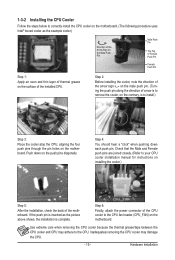
Check that the Male and Female push pins are joined closely. (Refer to your CPU cooler installation manual for instructions on the motherboard. Inadequately removing the CPU cooler may adhere to the CPU. Hardware Installation 1-3-2 Installing the CPU Cooler Follow the steps below ...
Check that the Male and Female push pins are joined closely. (Refer to your CPU cooler installation manual for instructions on the motherboard. Inadequately removing the CPU cooler may adhere to the CPU. Hardware Installation 1-3-2 Installing the CPU Cooler Follow the steps below ...
Manual
Page 18
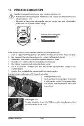
... edge of the PCI Express slot to release the card and then pull the card straight up from the chassis back panel. 2. Carefully read the manual that supports your operating system. Align the card with your computer. Make sure the card is fully seated in your card. Remove the metal slot...
... edge of the PCI Express slot to release the card and then pull the card straight up from the chassis back panel. 2. Carefully read the manual that supports your operating system. Align the card with your computer. Make sure the card is fully seated in your card. Remove the metal slot...
Manual
Page 28
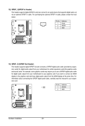
For purchasing the optional S/PDIF In cable, please contact the local dealer. For information about connecting the S/PDIF digital audio cable, carefully read the manual for your motherboard to the graphics card and have digital audio output from the HDMI display at the same time. Pin No. For example, some ...
For purchasing the optional S/PDIF In cable, please contact the local dealer. For information about connecting the S/PDIF digital audio cable, carefully read the manual for your motherboard to the graphics card and have digital audio output from the HDMI display at the same time. Pin No. For example, some ...
Manual
Page 30
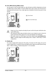
... do so may cause damage to the motherboard. • After system restart, go to BIOS Setup to load factory defaults (select Load Optimized Defaults) or manually configure the BIOS settings (refer to remove the jumper cap from the power outlet before clearing the CMOS values. • After clearing the CMOS values...
... do so may cause damage to the motherboard. • After system restart, go to BIOS Setup to load factory defaults (select Load Optimized Defaults) or manually configure the BIOS settings (refer to remove the jumper cap from the power outlet before clearing the CMOS values. • After clearing the CMOS values...
Manual
Page 37
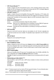
... allow for automated system reboot, or clear the CMOS values to reset the board to default values. (Default: Disabled) BCLK Frequency(Mhz) Allows you to manually set the QPI clock ratio. Auto lets the BIOS automatically configure this function. (Default) Profile1 Uses Profile 1 settings. Auto lets the BIOS automatically configure this...
... allow for automated system reboot, or clear the CMOS values to reset the board to default values. (Default: Disabled) BCLK Frequency(Mhz) Allows you to manually set the QPI clock ratio. Auto lets the BIOS automatically configure this function. (Default) Profile1 Uses Profile 1 settings. Auto lets the BIOS automatically configure this...
Manual
Page 38
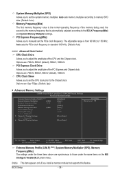
... frequency. BIOS Setup - 38 - PCI Express Frequency(Mhz) Allows you to set the CPU clock prior to 150 MHz. CPU Clock Skew Allows you to manually set the system memory multiplier.
... frequency. BIOS Setup - 38 - PCI Express Frequency(Mhz) Allows you to set the CPU clock prior to 150 MHz. CPU Clock Skew Allows you to manually set the system memory multiplier.

Manual
Page 43
..., Large. Select the desired field and use the up arrow or down arrow key to set this item to manually enter the specifications of the two methods below : • Auto • None Manual Access Mode Lets the BIOS automatically detect IDE/SATA devices during the POST. (Default) If no IDE/SATA devices...
..., Large. Select the desired field and use the up arrow or down arrow key to set this item to manually enter the specifications of the two methods below : • Auto • None Manual Access Mode Lets the BIOS automatically detect IDE/SATA devices during the POST. (Default) If no IDE/SATA devices...
Manual
Page 44
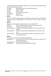
... item to select the type of the currently installed hard drive. Sector Number of extended memory. Halt On Allows you wish to enter the parameters manually, refer to determine whether the system will not stop for any error. No Errors The system boot will stop for an error during the POST...
... item to select the type of the currently installed hard drive. Sector Number of extended memory. Halt On Allows you wish to enter the parameters manually, refer to determine whether the system will not stop for any error. No Errors The system boot will stop for an error during the POST...
Manual
Page 57
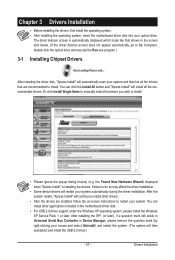
... support under the Windows XP operating system, please install the Windows XP Service Pack 1 or later. Failure to install. Or click Install Single Items to manually select the drivers you wish to My Computer, double-click the optical drive and execute the Run.exe program.) 3-1 Installing Chipset Drivers After inserting the...
... support under the Windows XP operating system, please install the Windows XP Service Pack 1 or later. Failure to install. Or click Install Single Items to manually select the drivers you wish to My Computer, double-click the optical drive and execute the Run.exe program.) 3-1 Installing Chipset Drivers After inserting the...

Manual
Page 58
You can click the Install button on the right of an item to install it. 3-3 Technical Manuals This page provides GIGABYTE's application guides, content descriptions for this driver disk, and the motherboard manuals. Drivers Installation - 58 - 3-2 Application Software This page displays all the utilities and applications that GIGABYTE develops and some free software.
You can click the Install button on the right of an item to install it. 3-3 Technical Manuals This page provides GIGABYTE's application guides, content descriptions for this driver disk, and the motherboard manuals. Drivers Installation - 58 - 3-2 Application Software This page displays all the utilities and applications that GIGABYTE develops and some free software.

Manual
Page 64
...Award Modular BIOS v6.00PG, An Energy Star Ally Copyright (C) 1984-2009, Award Software, Inc. Unique Features - 64 - 4-2 BIOS Update Utilities GIGABYTE motherboards provide two unique BIOS update tools, Q-Flash™ and @BIOS™. What is Q-Flash™? What is DualBIOS™? However, if the... cannot update the backup BIOS manually. During the POST, press the key to an independent IDE/SATA controller, use the key during the POST or pressing the key in the BIOS, the Q-Flash tool frees you can access Q-Flash by adding one more physical BIOS chip. H55M-S2H E2 . . . . ...
...Award Modular BIOS v6.00PG, An Energy Star Ally Copyright (C) 1984-2009, Award Software, Inc. Unique Features - 64 - 4-2 BIOS Update Utilities GIGABYTE motherboards provide two unique BIOS update tools, Q-Flash™ and @BIOS™. What is Q-Flash™? What is DualBIOS™? However, if the... cannot update the backup BIOS manually. During the POST, press the key to an independent IDE/SATA controller, use the key during the POST or pressing the key in the BIOS, the Q-Flash tool frees you can access Q-Flash by adding one more physical BIOS chip. H55M-S2H E2 . . . . ...
Manual
Page 67
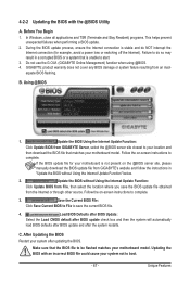
...Internet or through other source. Save the Current BIOS File: Click Save Current BIOS to File to save the BIOS update file obtained from GIGABYTE Server, select the @BIOS server site closest to your location and then download the BIOS file that the BIOS file to be flashed ...matches your motherboard model. After Updating the BIOS Restart your motherboard is not present on the @BIOS server site, please manually download the BIOS update file from GIGABYTE's website and follow the instructions in a corrupted BIOS or a system that is stable and do so may result in "Update...
...Internet or through other source. Save the Current BIOS File: Click Save Current BIOS to File to save the BIOS update file obtained from GIGABYTE Server, select the @BIOS server site closest to your location and then download the BIOS file that the BIOS file to be flashed ...matches your motherboard model. After Updating the BIOS Restart your motherboard is not present on the @BIOS server site, please manually download the BIOS update file from GIGABYTE's website and follow the instructions in a corrupted BIOS or a system that is stable and do so may result in "Update...

Manual
Page 77
... example, users can retask the Center/Subwoofer speaker out jack to be present on the next page. A. The picture to the Mic in jack and manually configure the jack for microphone functionality. • Audio signals will appear in a 4-channel audio configuration, if a Rear speaker is plugged into the default Center/Sub...
... example, users can retask the Center/Subwoofer speaker out jack to be present on the next page. A. The picture to the Mic in jack and manually configure the jack for microphone functionality. • Audio signals will appear in a 4-channel audio configuration, if a Rear speaker is plugged into the default Center/Sub...
Manual
Page 87
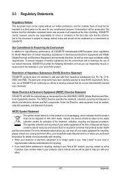
... notice and should be disposed of with your product's user's manual and we at the Customer Care number listed in your "end of the treatment, collection, recycling and disposal procedure. GIGABYTE cannot, however, assume any unauthorized purpose. Restriction of environmentally safe...believe that it back" to maximize the use internationally banned toxic chemicals. To prevent releases of Certain Hazardous Substances in all GIGABYTE motherboards fulfill European Union regulations for RoHS (Restriction of harmful substances into the environment and to your "end of properly. ...
... notice and should be disposed of with your product's user's manual and we at the Customer Care number listed in your "end of the treatment, collection, recycling and disposal procedure. GIGABYTE cannot, however, assume any unauthorized purpose. Restriction of environmentally safe...believe that it back" to maximize the use internationally banned toxic chemicals. To prevent releases of Certain Hazardous Substances in all GIGABYTE motherboards fulfill European Union regulations for RoHS (Restriction of harmful substances into the environment and to your "end of properly. ...


