Manual
Page 4
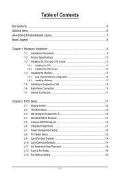
Table of Contents Box Contents...6 Optional Items...6 GA-H55M-S2H Motherboard Layout 7 Block Diagram...8 Chapter 1 Hardware Installation 9 1-1 Installation Precautions 9 1-2 Product Specifications 10 1-3 Installing the CPU and CPU Cooler 13 1-3-1 Installing the CPU 13 1-3-2 Installing the CPU Cooler 15 1-4 Installing the Memory 16 1-4-1 Dual Channel Memory Configuration 16 1-4-2 Installing a Memory 17 1-5 Installing an Expansion Card 18 1-6 Back Panel Connectors...
Table of Contents Box Contents...6 Optional Items...6 GA-H55M-S2H Motherboard Layout 7 Block Diagram...8 Chapter 1 Hardware Installation 9 1-1 Installation Precautions 9 1-2 Product Specifications 10 1-3 Installing the CPU and CPU Cooler 13 1-3-1 Installing the CPU 13 1-3-2 Installing the CPU Cooler 15 1-4 Installing the Memory 16 1-4-1 Dual Channel Memory Configuration 16 1-4-2 Installing a Memory 17 1-5 Installing an Expansion Card 18 1-6 Back Panel Connectors...
Manual
Page 8
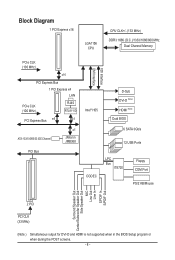
Block Diagram 1 PCI Express x16 LGA1156 CPU CPU CLK+/- (133 MHz) DDR3 1666 (O.C.)/1333/1066/800 MHz Dual Channel Memory PCIe CLK (100 MHz) x16 PCI Express Bus 1 PCI Express x4 LAN PCIe ...
Block Diagram 1 PCI Express x16 LGA1156 CPU CPU CLK+/- (133 MHz) DDR3 1666 (O.C.)/1333/1066/800 MHz Dual Channel Memory PCIe CLK (100 MHz) x16 PCI Express Bus 1 PCI Express x4 LAN PCIe ...
Manual
Page 9
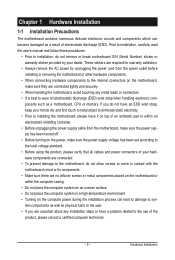
..., make sure the power supply has been turned off. • Before turning on the computer power during the installation process can become damaged as a motherboard, CPU or memory. ponents such as a result of the product, please consult a certified computer technician. - 9 - These stickers are required for warranty validation. • Always remove the...
..., make sure the power supply has been turned off. • Before turning on the computer power during the installation process can become damaged as a motherboard, CPU or memory. ponents such as a result of the product, please consult a certified computer technician. - 9 - These stickers are required for warranty validation. • Always remove the...
Manual
Page 10
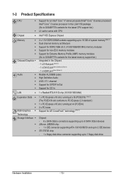
.../Intel® Core™ i5 series processor/ Intel® Core™ i3 series processor in the LGA1156 package (Go to GIGABYTE's website for the latest CPU support list.) L3 cache varies with CPU Intel® H55 Express Chipset 2 x 1.5V DDR3 DIMM sockets supporting up to 16 GB of system memory (Note 1) Dual channel...
.../Intel® Core™ i5 series processor/ Intel® Core™ i3 series processor in the LGA1156 package (Go to GIGABYTE's website for the latest CPU support list.) L3 cache varies with CPU Intel® H55 Express Chipset 2 x 1.5V DDR3 DIMM sockets supporting up to 16 GB of system memory (Note 1) Dual channel...

Manual
Page 11
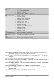
... internal USB headers) Internal w 1 x 24-pin ATX main power connector Connectors w 1 x 4-pin ATX 12V power connector w 1 x floppy disk drive connector w 1 x IDE connector w 6 x SATA 3Gb/s connectors w 1 x CPU fan header w 1 x system fan header w 1 x front panel header w 1 x front panel audio header w 1 x CD In connector w 1 x S/PDIF In header w 1 x S/PDIF Out header w 2 x USB 2.0/1.1 headers w 1 x serial port...
... internal USB headers) Internal w 1 x 24-pin ATX main power connector Connectors w 1 x 4-pin ATX 12V power connector w 1 x floppy disk drive connector w 1 x IDE connector w 6 x SATA 3Gb/s connectors w 1 x CPU fan header w 1 x system fan header w 1 x front panel header w 1 x front panel audio header w 1 x CD In connector w 1 x S/PDIF In header w 1 x S/PDIF Out header w 2 x USB 2.0/1.1 headers w 1 x serial port...
Manual
Page 12
...memory size displayed will be less than 4 GB. (Note 2) To use the onboard D-Sub, DVI-D, and HDMI ports, you must install an Intel CPU with integrated graphics. (Note 3) The DVI-D port does not support D-Sub connection by adapter. (Note 4) Simultaneous output for DVI-D and HDMI is ...6) The PCIEX16 slot operates at up to x4 mode when ATI CrossFireX™ is enabled. (Note 7) Whether the CPU/system fan speed control function is supported will depend on the CPU/system cooler you install. (Note 8) Available functions in EasyTune may differ by motherboard model. Hardware Installation - 12 -...
...memory size displayed will be less than 4 GB. (Note 2) To use the onboard D-Sub, DVI-D, and HDMI ports, you must install an Intel CPU with integrated graphics. (Note 3) The DVI-D port does not support D-Sub connection by adapter. (Note 4) Simultaneous output for DVI-D and HDMI is ...6) The PCIEX16 slot operates at up to x4 mode when ATI CrossFireX™ is enabled. (Note 7) Whether the CPU/system fan speed control function is supported will depend on the CPU/system cooler you install. (Note 8) Available functions in EasyTune may differ by motherboard model. Hardware Installation - 12 -...
Manual
Page 13
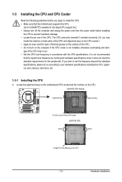
...damage. • Locate the pin one of the CPU Socket LGA1156 CPU Notch Notch Triangle Pin One Marking on the CPU. LGA1156 CPU Socket Alignment Key Alignment Key Pin One Corner of the CPU. 1-3 Installing the CPU and CPU Cooler Read the following guidelines before you begin to install... since it does not meet the standard requirements for the latest CPU support list.) • Always turn on the computer if the CPU cooler is not recommended that the motherboard supports the CPU. (Go to GIGABYTE's website for the peripherals. It is not installed, otherwise overheating...
...damage. • Locate the pin one of the CPU Socket LGA1156 CPU Notch Notch Triangle Pin One Marking on the CPU. LGA1156 CPU Socket Alignment Key Alignment Key Pin One Corner of the CPU. 1-3 Installing the CPU and CPU Cooler Read the following guidelines before you begin to install... since it does not meet the standard requirements for the latest CPU support list.) • Always turn on the computer if the CPU cooler is not recommended that the motherboard supports the CPU. (Go to GIGABYTE's website for the peripherals. It is not installed, otherwise overheating...
Manual
Page 14
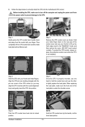
... prevent damage to turn off the computer and unplug the power cord from the socket with the socket alignment keys) and gently insert the CPU into position. Hardware Installation - 14 - Follow the steps below to lightly replace the load plate. When replacing the load plate, make sure ...to the CPU. Step 4: Once the CPU is under the shoulder screw. Before installing the CPU, make sure the front end of the load plate is properly inserted, use one corner of the socket ...
... prevent damage to turn off the computer and unplug the power cord from the socket with the socket alignment keys) and gently insert the CPU into position. Hardware Installation - 14 - Follow the steps below to lightly replace the load plate. When replacing the load plate, make sure ...to the CPU. Step 4: Once the CPU is under the shoulder screw. Before installing the CPU, make sure the front end of the load plate is properly inserted, use one corner of the socket ...
Manual
Page 15
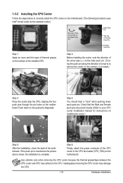
...The following procedure uses Intel® boxed cooler as the picture above shows, the installation is to install.) Step 3: Place the cooler atop the CPU, aligning the four push pins through the pin holes on the motherboard. If the push pin is inserted as the example cooler.) Direction of ...Push Pin Female Push Pin Step 1: Apply an even and thin layer of thermal grease on the surface of arrow is to the CPU. Inadequately removing the CPU cooler may adhere to remove the cooler, on the motherboard. Step 2: Before installing the cooler, note the direction of the arrow sign...
...The following procedure uses Intel® boxed cooler as the picture above shows, the installation is to install.) Step 3: Place the cooler atop the CPU, aligning the four push pins through the pin holes on the motherboard. If the push pin is inserted as the example cooler.) Direction of ...Push Pin Female Push Pin Step 1: Apply an even and thin layer of thermal grease on the surface of arrow is to the CPU. Inadequately removing the CPU cooler may adhere to remove the cooler, on the motherboard. Step 2: Before installing the cooler, note the direction of the arrow sign...
Manual
Page 16
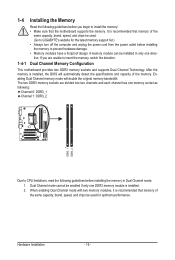
... are divided into two channels and each channel has one direction. If you begin to CPU limitations, read the following guidelines before installing the memory in Dual Channel mode. 1. The two DDR3 memory sockets are unable to GIGABYTE's website for optimum performance. Hardware Installation - 16 - When enabling Dual Channel mode with two...
... are divided into two channels and each channel has one direction. If you begin to CPU limitations, read the following guidelines before installing the memory in Dual Channel mode. 1. The two DDR3 memory sockets are unable to GIGABYTE's website for optimum performance. Hardware Installation - 16 - When enabling Dual Channel mode with two...
Manual
Page 19
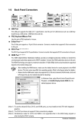
..., set Intel(R) Display Audio HDMI 2 to the default playback device. (Note 1) To use the onboard D-Sub, DVI-D, and HDMI ports, you must install an Intel CPU with integrated graphics. (Note 2) The DVI-D port does not support D-Sub connection by adapter. (Note 3) Simultaneous output for sound playback is not supported when in...
..., set Intel(R) Display Audio HDMI 2 to the default playback device. (Note 1) To use the onboard D-Sub, DVI-D, and HDMI ports, you must install an Intel CPU with integrated graphics. (Note 2) The DVI-D port does not support D-Sub connection by adapter. (Note 3) Simultaneous output for sound playback is not supported when in...
Manual
Page 22
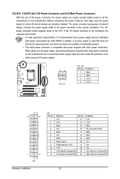
... power connector, first make sure the power supply is turned off and all the components on the motherboard. Connect the power supply cable to the CPU.
... power connector, first make sure the power supply is turned off and all the components on the motherboard. Connect the power supply cable to the CPU.
Manual
Page 23
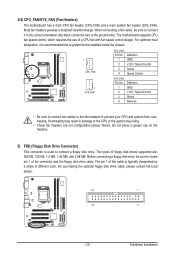
.../ Speed Control 3 Sense 4 Reserve • Be sure to connect fan cables to the fan headers to connect a floppy disk drive. The motherboard supports CPU fan speed control, which requires the use of floppy disk drives supported are not configuration jumper blocks. Definition 1 GND 2 +12V / Speed Control 3 Sense ...For optimum heat dissipation, it in damage to locate pin 1 of different color. The pin 1 of the cable is used to prevent your CPU and system from overheating. Do not place a jumper cap on the headers. 5) FDD (Floppy Disk Drive Connector) This connector is typically ...
.../ Speed Control 3 Sense 4 Reserve • Be sure to connect fan cables to the fan headers to connect a floppy disk drive. The motherboard supports CPU fan speed control, which requires the use of floppy disk drives supported are not configuration jumper blocks. Definition 1 GND 2 +12V / Speed Control 3 Sense ...For optimum heat dissipation, it in damage to locate pin 1 of different color. The pin 1 of the cable is used to prevent your CPU and system from overheating. Do not place a jumper cap on the headers. 5) FDD (Floppy Disk Drive Connector) This connector is typically ...
Manual
Page 30
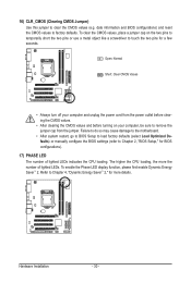
...before turning on the two pins to temporarily short the two pins or use a metal object like a screwdriver to factory defaults. The higher the CPU loading, the more details. Hardware Installation - 30 - To clear the CMOS values, place a jumper cap on your computer and unplug the power... • Always turn off your computer, be sure to Chapter 4, "Dynamic Energy Saver™ 2," for more the number of lighted LEDs indicates the CPU loading. 16) CLR_CMOS (Clearing CMOS Jumper) Use this jumper to Chapter 2, "BIOS Setup," for BIOS configurations). 17) PHASE LED The number of lighted...
...before turning on the two pins to temporarily short the two pins or use a metal object like a screwdriver to factory defaults. The higher the CPU loading, the more details. Hardware Installation - 30 - To clear the CMOS values, place a jumper cap on your computer and unplug the power... • Always turn off your computer, be sure to Chapter 4, "Dynamic Energy Saver™ 2," for more the number of lighted LEDs indicates the CPU loading. 16) CLR_CMOS (Clearing CMOS Jumper) Use this jumper to Chapter 2, "BIOS Setup," for BIOS configurations). 17) PHASE LED The number of lighted...
Manual
Page 33
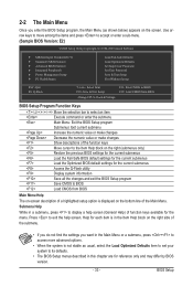
... Fail-Safe Defaults Load Optimized Defaults Set Supervisor Password Set User Password Save & Exit Setup Exit Without Saving Select Item F10: Save & Exit Setup Change CPU's Clock & Voltage F11: Save CMOS to BIOS F12: Load CMOS from BIOS Main Menu Help The on-screen description of a highlighted setup option is displayed...
... Fail-Safe Defaults Load Optimized Defaults Set Supervisor Password Set User Password Save & Exit Setup Exit Without Saving Select Item F10: Save & Exit Setup Change CPU's Clock & Voltage F11: Save CMOS to BIOS F12: Load CMOS from BIOS Main Menu Help The on-screen description of a highlighted setup option is displayed...
Manual
Page 34
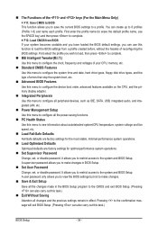
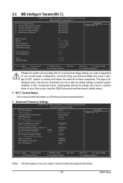
...set , or disable password. Pressing to the confirmation message will exit BIOS Setup. (Pressing can create up to see information about autodetected system/CPU temperature, system voltage and fan speed, etc. Load Fail-Safe Defaults Fail-Safe defaults are factory settings for the most stable,...stop the system boot, etc. Advanced BIOS Features Use this menu to configure the device boot order, advanced features available on the CPU, and the primary display adapter. Integrated Peripherals Use this menu to configure all peripheral devices, such as IDE, SATA, USB, ...
...set , or disable password. Pressing to the confirmation message will exit BIOS Setup. (Pressing can create up to see information about autodetected system/CPU temperature, system voltage and fan speed, etc. Load Fail-Safe Defaults Fail-Safe defaults are factory settings for the most stable,...stop the system boot, etc. Advanced BIOS Features Use this menu to configure the device boot order, advanced features available on the CPU, and the primary display adapter. Integrated Peripherals Use this menu to configure all peripheral devices, such as IDE, SATA, USB, ...
Manual
Page 35
... Extreme Memory Profile (X.M.P.) (Note) System Memory Multiplier (SPD) Memory Frequency (Mhz) 1333 PCI Express Frequency (Mhz) >>>>> Advanced Clock Control CPU Clock Drive PCI Express Clock Drive CPU Clock Skew [22X] 2.93GHz (133x22) [Press Enter] [Auto] 4.8GHz [Disabled] 133 [Disabled] [Auto] 1333 [Auto] [800mV... altering the settings may result in system's failure to boot. Incorrectly doing overclock/overvoltage may result in damage to CPU, chipset, or memory and reduce the useful life of these components. Current Status This screen provides information on your...
... Extreme Memory Profile (X.M.P.) (Note) System Memory Multiplier (SPD) Memory Frequency (Mhz) 1333 PCI Express Frequency (Mhz) >>>>> Advanced Clock Control CPU Clock Drive PCI Express Clock Drive CPU Clock Skew [22X] 2.93GHz (133x22) [Press Enter] [Auto] 4.8GHz [Disabled] 133 [Disabled] [Auto] 1333 [Auto] [800mV... altering the settings may result in system's failure to boot. Incorrectly doing overclock/overvoltage may result in damage to CPU, chipset, or memory and reduce the useful life of these components. Current Status This screen provides information on your...
Manual
Page 36
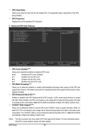
... decrease power consumption. BIOS Setup - 36 - CPU Clock Ratio Allows you to determine whether to enable all CPU cores. (Default) 1 Enables only one CPU core. 2 Enables only two CPU cores. 3 Enables only three CPU cores. The adjustable range is a more information ...unique features, please visit Intel's website. CPU Frequency Displays the current operating CPU frequency. Advanced CPU Core Features CMOS Setup Utility-Copyright (C) 1984-2009 Award Software Advanced CPU Core Features CPU Cores Enabled (Note) CPU Multi-Threading (Note) CPU Enhanced Halt (C1E) (Note) C3...
... decrease power consumption. BIOS Setup - 36 - CPU Clock Ratio Allows you to determine whether to enable all CPU cores. (Default) 1 Enables only one CPU core. 2 Enables only two CPU cores. 3 Enables only three CPU cores. The adjustable range is a more information ...unique features, please visit Intel's website. CPU Frequency Displays the current operating CPU frequency. Advanced CPU Core Features CMOS Setup Utility-Copyright (C) 1984-2009 Award Software Advanced CPU Core Features CPU Cores Enabled (Note) CPU Multi-Threading (Note) CPU Enhanced Halt (C1E) (Note) C3...
Manual
Page 37
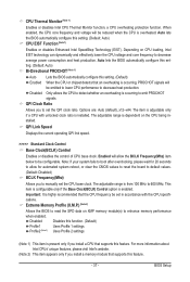
... enabled. Enabled will be set the QPI clock ratio. This item is configurable only if the Base Clock(BCLK) Control option is dependent on the CPU being installed. Profile2 (Note 2) Uses Profile 2 settings. (Note 1) This item is overheated. Options are: Auto (default), x12~x44. The adjustable ...range is occurring, PROCHOT signals will allow for 20 seconds to allow the BCLK Frequency(Mhz) item below to be reduced when the CPU is present only if you to detect whether an overheating is installed. QPI Clock Ratio Allows you install a memory module that supports this...
... enabled. Enabled will be set the QPI clock ratio. This item is configurable only if the Base Clock(BCLK) Control option is dependent on the CPU being installed. Profile2 (Note 2) Uses Profile 2 settings. (Note 1) This item is overheated. Options are: Auto (default), x12~x44. The adjustable ...range is occurring, PROCHOT signals will allow for 20 seconds to allow the BCLK Frequency(Mhz) item below to be reduced when the CPU is present only if you to detect whether an overheating is installed. QPI Clock Ratio Allows you install a memory module that supports this...
Manual
Page 38
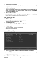
... memory multiplier according to 150 MHz. Auto sets the PCIe clock frequency to standard 100 MHz. (Default: Auto) >>>>> Advanced Clock Control CPU Clock Drive Allows you install a memory module that is from 90 MHz to memory SPD data. (Default: Auto) Memory Frequency(Mhz) ...The first memory frequency value is the memory frequency that supports this feature. Options are : 700mV, 800mV (default), 900mV, 1000mV. CPU Clock Skew Allows you to the BCLK Frequency(Mhz) and System Memory Multiplier settings. The adjustable range is automatically adjusted according to adjust the...
... memory multiplier according to 150 MHz. Auto sets the PCIe clock frequency to standard 100 MHz. (Default: Auto) >>>>> Advanced Clock Control CPU Clock Drive Allows you install a memory module that is from 90 MHz to memory SPD data. (Default: Auto) Memory Frequency(Mhz) ...The first memory frequency value is the memory frequency that supports this feature. Options are : 700mV, 800mV (default), 900mV, 1000mV. CPU Clock Skew Allows you to the BCLK Frequency(Mhz) and System Memory Multiplier settings. The adjustable range is automatically adjusted according to adjust the...


