Manual
Page 1
GA-H55M-S2H LGA1156 socket motherboard for Intel® Core™ i7 processor family/ Intel® Core™ i5 processor family/ Intel® Core™ i3 processor family User's Manual Rev. 1001 12ME-H55MS2H-1001R
GA-H55M-S2H LGA1156 socket motherboard for Intel® Core™ i7 processor family/ Intel® Core™ i5 processor family/ Intel® Core™ i3 processor family User's Manual Rev. 1001 12ME-H55MS2H-1001R
Manual
Page 2
Motherboard GA-H55M-S2H Dec. 7, 2009 Motherboard GA-H55M-S2H Dec. 7, 2009
Motherboard GA-H55M-S2H Dec. 7, 2009 Motherboard GA-H55M-S2H Dec. 7, 2009
Manual
Page 3
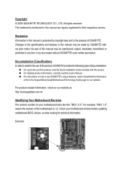
... product-related information, check on our website at: http://www.gigabyte.com.tw Identifying Your Motherboard Revision The revision number on our website. Example: The trademarks mentioned in the use GIGABYTE's unique features, read the User's Manual. For detailed product ... "REV: X.X." Copyright © 2009 GIGA-BYTE TECHNOLOGY CO., LTD. Check your motherboard looks like this manual may be made by GIGABYTE without GIGABYTE's prior written permission. Changes to use of GIGABYTE. Disclaimer Information in any form or by copyright laws and is 1.0. For example,...
... product-related information, check on our website at: http://www.gigabyte.com.tw Identifying Your Motherboard Revision The revision number on our website. Example: The trademarks mentioned in the use GIGABYTE's unique features, read the User's Manual. For detailed product ... "REV: X.X." Copyright © 2009 GIGA-BYTE TECHNOLOGY CO., LTD. Check your motherboard looks like this manual may be made by GIGABYTE without GIGABYTE's prior written permission. Changes to use of GIGABYTE. Disclaimer Information in any form or by copyright laws and is 1.0. For example,...
Manual
Page 4
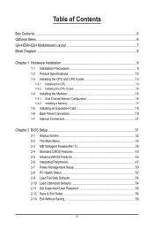
Table of Contents Box Contents...6 Optional Items...6 GA-H55M-S2H Motherboard Layout 7 Block Diagram...8 Chapter 1 Hardware Installation 9 1-1 Installation Precautions 9 1-2 Product Specifications 10 1-3 Installing the CPU and CPU Cooler 13 1-3-1 Installing the CPU 13 1-3-2 Installing the CPU ...
Table of Contents Box Contents...6 Optional Items...6 GA-H55M-S2H Motherboard Layout 7 Block Diagram...8 Chapter 1 Hardware Installation 9 1-1 Installation Precautions 9 1-2 Product Specifications 10 1-3 Installing the CPU and CPU Cooler 13 1-3-1 Installing the CPU 13 1-3-2 Installing the CPU ...
Manual
Page 6
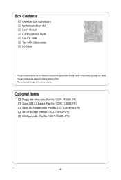
...-1UB030-5*R) 2-port SATA power cable (Part No. 12CF1-2SERPW-0*R) S/PDIF In cable (Part No. 12CR1-1SPDIN-0*R) COM port cable (Part No. 12CF1-1CM001-3*R) - 6 - Box Contents GA-H55M-S2H motherboard Motherboard driver disk User's Manual Quick Installation Guide One IDE cable Two SATA 3Gb/s cables I/O Shield • The box contents above are subject to change without...
...-1UB030-5*R) 2-port SATA power cable (Part No. 12CF1-2SERPW-0*R) S/PDIF In cable (Part No. 12CR1-1SPDIN-0*R) COM port cable (Part No. 12CF1-1CM001-3*R) - 6 - Box Contents GA-H55M-S2H motherboard Motherboard driver disk User's Manual Quick Installation Guide One IDE cable Two SATA 3Gb/s cables I/O Shield • The box contents above are subject to change without...
Manual
Page 7
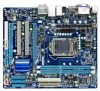
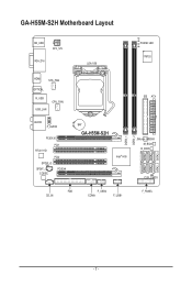
GA-H55M-S2H Motherboard Layout KB_USB ATX_12V VGA_DVI LGA1156 PHASE LED IT8720 HDMI SYS_FAN OPTICAL R_USB USB_LAN CPU_FAN AUDIO F_AUDIO PCIEX16 PCI1 RTL8111D PCI2 SPDIF_O SPDIF_I CODEC PCIEX4 IDE ATX BAT GA-H55M-S2H Intel® H55 JMicron JMB368 M_BIOS B_BIOS CLR_CMOS FDD CD_IN F_USB2 COMA F_USB1 F_PANEL DDR3_1 DDR3_2 SATA2_5 SATA2_2 SATA2_4 SATA2_1 SATA2_3 SATA2_0 - 7 -
GA-H55M-S2H Motherboard Layout KB_USB ATX_12V VGA_DVI LGA1156 PHASE LED IT8720 HDMI SYS_FAN OPTICAL R_USB USB_LAN CPU_FAN AUDIO F_AUDIO PCIEX16 PCI1 RTL8111D PCI2 SPDIF_O SPDIF_I CODEC PCIEX4 IDE ATX BAT GA-H55M-S2H Intel® H55 JMicron JMB368 M_BIOS B_BIOS CLR_CMOS FDD CD_IN F_USB2 COMA F_USB1 F_PANEL DDR3_1 DDR3_2 SATA2_5 SATA2_2 SATA2_4 SATA2_1 SATA2_3 SATA2_0 - 7 -
Manual
Page 9
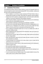
...for warranty validation. • Always remove the AC power by your hardware components are connected. • To prevent damage to the motherboard, do not allow screws to come in a high-temperature environment. • Turning on the computer power during the installation process can become ...have an ESD wrist strap, keep your hands dry and first touch a metal object to eliminate static electricity. • Prior to installing the motherboard, please have a problem related to the local voltage standard. • Before using the product, please verify that all cables and power connectors ...
...for warranty validation. • Always remove the AC power by your hardware components are connected. • To prevent damage to the motherboard, do not allow screws to come in a high-temperature environment. • Turning on the computer power during the installation process can become ...have an ESD wrist strap, keep your hands dry and first touch a metal object to eliminate static electricity. • Prior to installing the motherboard, please have a problem related to the local voltage standard. • Before using the product, please verify that all cables and power connectors ...
Manual
Page 12
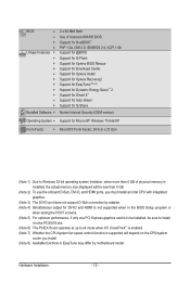
... CPU/system fan speed control function is supported will depend on the CPU/system cooler you install. (Note 8) Available functions in EasyTune may differ by motherboard model.
... CPU/system fan speed control function is supported will depend on the CPU/system cooler you install. (Note 8) Available functions in EasyTune may differ by motherboard model.
Manual
Page 13
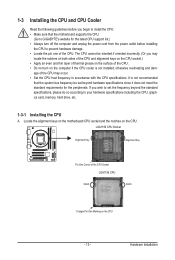
... the CPU to your hardware specifications including the CPU, graphics card, memory, hard drive, etc. 1-3-1 Installing the CPU A. Locate the alignment keys on the motherboard CPU socket and the notches on the surface of the CPU. • Do not turn off the computer and unplug the power cord from the... power outlet before you begin to install the CPU: • Make sure that the motherboard supports the CPU. (Go to GIGABYTE's website for the peripherals. age of the CPU may locate the notches on both sides of the CPU and alignment keys on the...
... the CPU to your hardware specifications including the CPU, graphics card, memory, hard drive, etc. 1-3-1 Installing the CPU A. Locate the alignment keys on the motherboard CPU socket and the notches on the surface of the CPU. • Do not turn off the computer and unplug the power cord from the... power outlet before you begin to install the CPU: • Make sure that the motherboard supports the CPU. (Go to GIGABYTE's website for the peripherals. age of the CPU may locate the notches on both sides of the CPU and alignment keys on the...
Manual
Page 14
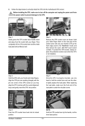
Step 5: Push the CPU socket lever back into the motherboard CPU socket. Align the CPU pin one marking (triangle) with your finger. NOTE: Hold the CPU socket lever by the handle, not the lever base ...
Step 5: Push the CPU socket lever back into the motherboard CPU socket. Align the CPU pin one marking (triangle) with your finger. NOTE: Hold the CPU socket lever by the handle, not the lever base ...
Manual
Page 15
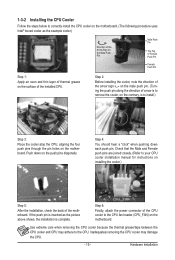
... of the CPU cooler to your CPU cooler installation manual for instructions on installing the cooler.) Step 5: After the installation, check the back of the motherboard. Use extreme care when removing the CPU cooler because the thermal grease/tape between the CPU cooler and CPU may damage the CPU. - 15 - ...the CPU cooler may adhere to install.) Step 3: Place the cooler atop the CPU, aligning the four push pins through the pin holes on the motherboard. If the push pin is inserted as the example cooler.) Direction of the Arrow Sign on the Male Push Pin Male Push Pin The Top...
... of the CPU cooler to your CPU cooler installation manual for instructions on installing the cooler.) Step 5: After the installation, check the back of the motherboard. Use extreme care when removing the CPU cooler because the thermal grease/tape between the CPU cooler and CPU may damage the CPU. - 15 - ...the CPU cooler may adhere to install.) Step 3: Place the cooler atop the CPU, aligning the four push pins through the pin holes on the motherboard. If the push pin is inserted as the example cooler.) Direction of the Arrow Sign on the Male Push Pin Male Push Pin The Top...
Manual
Page 16
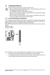
...speed, and chips be used . (Go to install the memory: • Make sure that memory of the memory. If you begin to GIGABYTE's website for optimum performance. The two DDR3 memory sockets are divided into two channels and each channel has one memory socket as following: Channel 0:... power cord from the power outlet before installing the memory to insert the memory, switch the direction. 1-4-1 Dual Channel Memory Configuration This motherboard provides two DDR3 memory sockets and supports Dual Channel Technology. Dual Channel mode cannot be installed in Dual Channel mode. 1. After the ...
...speed, and chips be used . (Go to install the memory: • Make sure that memory of the memory. If you begin to GIGABYTE's website for optimum performance. The two DDR3 memory sockets are divided into two channels and each channel has one memory socket as following: Channel 0:... power cord from the power outlet before installing the memory to insert the memory, switch the direction. 1-4-1 Dual Channel Memory Configuration This motherboard provides two DDR3 memory sockets and supports Dual Channel Technology. Dual Channel mode cannot be installed in Dual Channel mode. 1. After the ...
Manual
Page 17
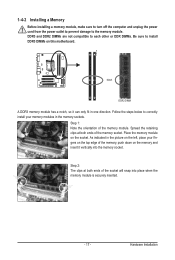
..., make sure to turn off the computer and unplug the power cord from the power outlet to prevent damage to install DDR3 DIMMs on this motherboard. Spread the retaining clips at both ends of the memory, push down on the memory and insert it can only fit in the memory sockets...
..., make sure to turn off the computer and unplug the power cord from the power outlet to prevent damage to install DDR3 DIMMs on this motherboard. Spread the retaining clips at both ends of the memory, push down on the memory and insert it can only fit in the memory sockets...
Manual
Page 18
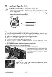
... turn off the computer and unplug the power cord from the power outlet before you begin to install an expansion card: • Make sure the motherboard supports the expansion card. Make sure the metal contacts on the top edge of the PCI Express slot to release the card and then pull...
... turn off the computer and unplug the power cord from the power outlet before you begin to install an expansion card: • Make sure the motherboard supports the expansion card. Make sure the metal contacts on the top edge of the PCI Express slot to release the card and then pull...
Manual
Page 20
... in a 7.1-channel audio configuration. Refer to the instructions on setting up to an external audio system that your device and then remove it from the motherboard. • When removing the cable, pull it side to side to perform different functions via the audio software. Connection/ Speed LED Activity LED LAN Port...
... in a 7.1-channel audio configuration. Refer to the instructions on setting up to an external audio system that your device and then remove it from the motherboard. • When removing the cable, pull it side to side to perform different functions via the audio software. Connection/ Speed LED Activity LED LAN Port...
Manual
Page 21
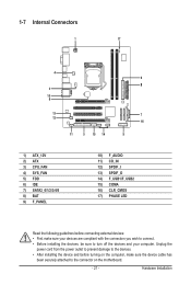
...) F_AUDIO 11) CD_IN 12) SPDIF_I 13) SPDIF_O 14) F_USB1/F_USB2 15) COMA 16) CLR_CMOS 17) PHASE LED Read the following guidelines before turning on the motherboard. - 21 - Unplug the power cord from the power outlet to prevent damage to the devices. • After installing the device and before connecting external devices...
...) F_AUDIO 11) CD_IN 12) SPDIF_I 13) SPDIF_O 14) F_USB1/F_USB2 15) COMA 16) CLR_CMOS 17) PHASE LED Read the following guidelines before turning on the motherboard. - 21 - Unplug the power cord from the power outlet to prevent damage to the devices. • After installing the device and before connecting external devices...
Manual
Page 22
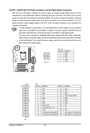
... for 2x12-pin ATX) - 22 - Before connecting the power connector, first make sure the power supply is turned off and all the components on the motherboard. If the 12V power connector is not connected, the computer will not start. • To meet expansion requirements, it is compatible with power supplies with... power supply cable into pins under the protective cover when using a 2x12 power supply, remove the protective cover from the main power connector on the motherboard.
... for 2x12-pin ATX) - 22 - Before connecting the power connector, first make sure the power supply is turned off and all the components on the motherboard. If the 12V power connector is not connected, the computer will not start. • To meet expansion requirements, it is compatible with power supplies with... power supply cable into pins under the protective cover when using a 2x12 power supply, remove the protective cover from the main power connector on the motherboard.
Manual
Page 23
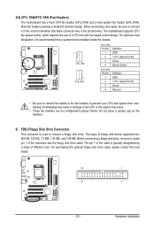
...Disk Drive Connector) This connector is typically designated by a stripe of floppy disk drives supported are not configuration jumper blocks. The motherboard supports CPU fan speed control, which requires the use of the connector and the floppy disk drive cable. For purchasing the ... the system may result in the correct orientation (the black connector wire is the ground wire). Hardware Installation 3/4) CPU_FAN/SYS_FAN (Fan Headers) The motherboard has a 4-pin CPU fan header (CPU_FAN) and a 4-pin system fan header (SYS_FAN). Overheating may hang. • These fan headers are...
...Disk Drive Connector) This connector is typically designated by a stripe of floppy disk drives supported are not configuration jumper blocks. The motherboard supports CPU fan speed control, which requires the use of the connector and the floppy disk drive cable. For purchasing the ... the system may result in the correct orientation (the black connector wire is the ground wire). Hardware Installation 3/4) CPU_FAN/SYS_FAN (Fan Headers) The motherboard has a 4-pin CPU fan header (CPU_FAN) and a 4-pin system fan header (SYS_FAN). Overheating may hang. • These fan headers are...
Manual
Page 27
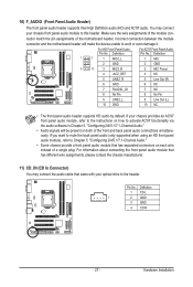
... drive to this header. You may connect the audio cable that has separated connectors on both of the motherboard header. Definition 1 CD-L 1 2 GND 3 GND 4 CD-R - 27 - Incorrect connection between the module connector and the motherboard header will be present on each wire instead of a single plug. For HD Front Panel Audio: For...
... drive to this header. You may connect the audio cable that has separated connectors on both of the motherboard header. Definition 1 CD-L 1 2 GND 3 GND 4 CD-R - 27 - Incorrect connection between the module connector and the motherboard header will be present on each wire instead of a single plug. For HD Front Panel Audio: For...
Manual
Page 28
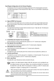
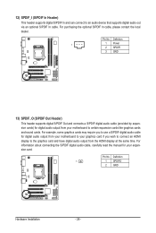
... cards like graphics cards and sound cards. For example, some graphics cards may require you to use a S/PDIF digital audio cable for your motherboard to an audio device that supports digital audio out via an optional S/PDIF In cable. For information about connecting the S/PDIF digital audio cable,... carefully read the manual for digital audio output from your motherboard to your graphics card if you wish to connect an HDMI display to the graphics card and have digital audio output from your expansion ...
... cards like graphics cards and sound cards. For example, some graphics cards may require you to use a S/PDIF digital audio cable for your motherboard to an audio device that supports digital audio out via an optional S/PDIF In cable. For information about connecting the S/PDIF digital audio cable,... carefully read the manual for digital audio output from your motherboard to your graphics card if you wish to connect an HDMI display to the graphics card and have digital audio output from your expansion ...


