Manual
Page 3
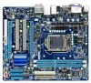
... information on/from the Support&Downloads\Motherboard\Technology Guide page on our website. For product-related information, check on our website at: http://www.gigabyte.com.tw Identifying Your Motherboard Revision The revision number on how to the specifications and features in this manual may be made by any form..., or when looking for technical information. Changes to use of the product, read the User's Manual. For detailed product information, carefully read the Quick Installation Guide included with the product. Copyright © 2009 GIGA-BYTE TECHNOLOGY CO., LTD.
... information on/from the Support&Downloads\Motherboard\Technology Guide page on our website. For product-related information, check on our website at: http://www.gigabyte.com.tw Identifying Your Motherboard Revision The revision number on how to the specifications and features in this manual may be made by any form..., or when looking for technical information. Changes to use of the product, read the User's Manual. For detailed product information, carefully read the Quick Installation Guide included with the product. Copyright © 2009 GIGA-BYTE TECHNOLOGY CO., LTD.
Manual
Page 4
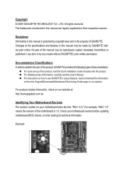
Table of Contents Box Contents...6 Optional Items...6 GA-H55M-S2H Motherboard Layout 7 Block Diagram...8 Chapter 1 Hardware Installation 9 1-1 Installation Precautions 9 1-2 Product Specifications 10 1-3 Installing the CPU and CPU Cooler 13 1-3-1 Installing the CPU 13 1-3-2 Installing the CPU Cooler 15 1-4 Installing the Memory 16 1-4-1 Dual Channel Memory Configuration 16 1-4-2 Installing a Memory 17 1-5 Installing an Expansion Card 18 1-6 Back Panel Connectors 19 1-7 Internal Connectors 21...
Table of Contents Box Contents...6 Optional Items...6 GA-H55M-S2H Motherboard Layout 7 Block Diagram...8 Chapter 1 Hardware Installation 9 1-1 Installation Precautions 9 1-2 Product Specifications 10 1-3 Installing the CPU and CPU Cooler 13 1-3-1 Installing the CPU 13 1-3-2 Installing the CPU Cooler 15 1-4 Installing the Memory 16 1-4-1 Dual Channel Memory Configuration 16 1-4-2 Installing a Memory 17 1-5 Installing an Expansion Card 18 1-6 Back Panel Connectors 19 1-7 Internal Connectors 21...
Manual
Page 5
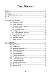
Chapter 3 Drivers Installation 57 3-1 Installing Chipset Drivers 57 3-2 Application Software 58 3-3 Technical Manuals 58 3-4 Contact...59 3-5 System...59 3-6 Download Center 60 3-7 New Utilities...60 Chapter 4 Unique Features 61 4-1 Xpress Recovery2 ...
Chapter 3 Drivers Installation 57 3-1 Installing Chipset Drivers 57 3-2 Application Software 58 3-3 Technical Manuals 58 3-4 Contact...59 3-5 System...59 3-6 Download Center 60 3-7 New Utilities...60 Chapter 4 Unique Features 61 4-1 Xpress Recovery2 ...
Manual
Page 6
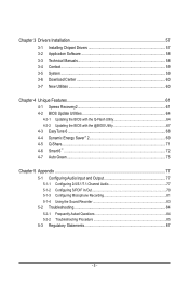
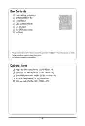
... cable (Part No. 12CF1-2SERPW-0*R) S/PDIF In cable (Part No. 12CR1-1SPDIN-0*R) COM port cable (Part No. 12CF1-1CM001-3*R) - 6 - Box Contents GA-H55M-S2H motherboard Motherboard driver disk User's Manual Quick Installation Guide One IDE cable Two SATA 3Gb/s cables I/O Shield • The box contents above are subject to change without notice. • The...
... cable (Part No. 12CF1-2SERPW-0*R) S/PDIF In cable (Part No. 12CR1-1SPDIN-0*R) COM port cable (Part No. 12CF1-1CM001-3*R) - 6 - Box Contents GA-H55M-S2H motherboard Motherboard driver disk User's Manual Quick Installation Guide One IDE cable Two SATA 3Gb/s cables I/O Shield • The box contents above are subject to change without notice. • The...
Manual
Page 9
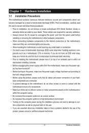
...are connected tightly and securely. • When handling the motherboard, avoid touching any metal leads or connectors. • It is best to installation, do not allow screws to come in a high-temperature environment. • Turning on the motherboard, make sure the power supply voltage has... the local voltage standard. • Before using the product, please verify that all cables and power connectors of your dealer. Prior to installation, carefully read the user's manual and follow these procedures: • Prior to wear an electrostatic discharge (ESD) wrist strap when handling ...
...are connected tightly and securely. • When handling the motherboard, avoid touching any metal leads or connectors. • It is best to installation, do not allow screws to come in a high-temperature environment. • Turning on the motherboard, make sure the power supply voltage has... the local voltage standard. • Before using the product, please verify that all cables and power connectors of your dealer. Prior to installation, carefully read the user's manual and follow these procedures: • Prior to wear an electrostatic discharge (ESD) wrist strap when handling ...
Manual
Page 10
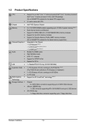
... Core™ i5 series processor/ Intel® Core™ i3 series processor in the LGA1156 package (Go to GIGABYTE's website for the latest CPU support list.) L3 cache varies with CPU Intel® H55 Express Chipset 2 x...for DDR3 1666 (O.C.)/1333/1066/800 MHz memory modules Support for non-ECC memory modules Support for Extreme Memory Profile (XMP) memory modules (Go to GIGABYTE's website for the latest memory support list.) Integrated in the Chipset: - 1 x D-Sub port (Note 2) - 1 x DVI-D port (...1 x floppy disk drive connector supporting up to 1 floppy disk drive Hardware Installation - 10 -
... Core™ i5 series processor/ Intel® Core™ i3 series processor in the LGA1156 package (Go to GIGABYTE's website for the latest CPU support list.) L3 cache varies with CPU Intel® H55 Express Chipset 2 x...for DDR3 1666 (O.C.)/1333/1066/800 MHz memory modules Support for non-ECC memory modules Support for Extreme Memory Profile (XMP) memory modules (Go to GIGABYTE's website for the latest memory support list.) Integrated in the Chipset: - 1 x D-Sub port (Note 2) - 1 x DVI-D port (...1 x floppy disk drive connector supporting up to 1 floppy disk drive Hardware Installation - 10 -

Manual
Page 11
... fan speed detection CPU overheating warning CPU/System fan fail warning CPU/System fan speed control (Note 7) - 11 - USB Integrated in the Chipset - Hardware Installation
... fan speed detection CPU overheating warning CPU/System fan fail warning CPU/System fan speed control (Note 7) - 11 - USB Integrated in the Chipset - Hardware Installation
Manual
Page 12
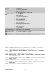
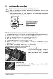
...0a, DMI 2.0, SM BIOS 2.4, ACPI 1.0b Support for @BIOS Support for Q-Flash Support for Xpress BIOS Rescue Support for Download Center Support for Xpress Install Support for Xpress Recovery2 Support for EasyTune (Note 8) Support for Dynamic Energy Saver™ 2 Support for Smart 6™ Support for Auto Green Support for... Setup program or when during the POST screens. (Note 5) For optimum performance, if only one PCI Express graphics card is to be installed, be sure to install it in the PCIEX16 slot. (Note 6) The PCIEX16 slot operates at up to x4 mode when ATI CrossFireX™ is enabled. (...
...0a, DMI 2.0, SM BIOS 2.4, ACPI 1.0b Support for @BIOS Support for Q-Flash Support for Xpress BIOS Rescue Support for Download Center Support for Xpress Install Support for Xpress Recovery2 Support for EasyTune (Note 8) Support for Dynamic Energy Saver™ 2 Support for Smart 6™ Support for Auto Green Support for... Setup program or when during the POST screens. (Note 5) For optimum performance, if only one PCI Express graphics card is to be installed, be sure to install it in the PCIEX16 slot. (Note 6) The PCIEX16 slot operates at up to x4 mode when ATI CrossFireX™ is enabled. (...
Manual
Page 13
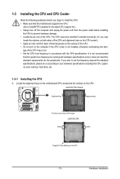
... age of the CPU. • Do not turn off the computer and unplug the power cord from the power outlet before you begin to install the CPU: • Make sure that the system bus frequency be inserted if oriented incorrectly. (Or you wish to set beyond the standard... specifications, please do so according to GIGABYTE's website for the peripherals. It is not installed, otherwise overheating and dam- The CPU cannot be set the frequency beyond hardware specifications since it does not meet the...
... age of the CPU. • Do not turn off the computer and unplug the power cord from the power outlet before you begin to install the CPU: • Make sure that the system bus frequency be inserted if oriented incorrectly. (Or you wish to set beyond the standard... specifications, please do so according to GIGABYTE's website for the peripherals. It is not installed, otherwise overheating and dam- The CPU cannot be set the frequency beyond hardware specifications since it does not meet the...
Manual
Page 14
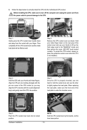
... pin one hand to hold the socket lever and use your index finger down and away from the power outlet to prevent damage to correctly install the CPU into the motherboard CPU socket. NOTE: Hold the CPU socket lever by the handle, not the lever base portion. Then completely lift the... power cord from the socket with your finger. Step 5: Push the CPU socket lever back into position. Follow the steps below to the CPU. B. Before installing the CPU, make sure the front end of the load plate is properly inserted, use one corner of the socket cover and use the other...
... pin one hand to hold the socket lever and use your index finger down and away from the power outlet to prevent damage to correctly install the CPU into the motherboard CPU socket. NOTE: Hold the CPU socket lever by the handle, not the lever base portion. Then completely lift the... power cord from the socket with your finger. Step 5: Push the CPU socket lever back into position. Follow the steps below to the CPU. B. Before installing the CPU, make sure the front end of the load plate is properly inserted, use one corner of the socket cover and use the other...
Manual
Page 15
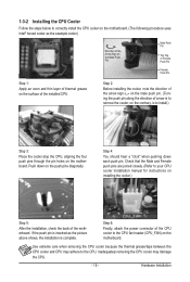
... Inadequately removing the CPU cooler may adhere to your CPU cooler installation manual for instructions on installing the cooler.) Step 5: After the installation, check the back of the installed CPU. 1-3-2 Installing the CPU Cooler Follow the steps below to correctly install the CPU cooler on the motherboard. (The following procedure uses ...the male push pin. (Turning the push pin along the direction of arrow is to remove the cooler, on the contrary, is to install.) Step 3: Place the cooler atop the CPU, aligning the four push pins through the pin holes on the surface of the motherboard....
... Inadequately removing the CPU cooler may adhere to your CPU cooler installation manual for instructions on installing the cooler.) Step 5: After the installation, check the back of the installed CPU. 1-3-2 Installing the CPU Cooler Follow the steps below to correctly install the CPU cooler on the motherboard. (The following procedure uses ...the male push pin. (Turning the push pin along the direction of arrow is to remove the cooler, on the contrary, is to install.) Step 3: Place the cooler atop the CPU, aligning the four push pins through the pin holes on the surface of the motherboard....
Manual
Page 16
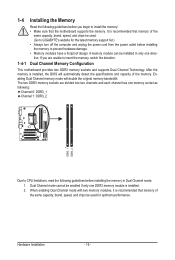
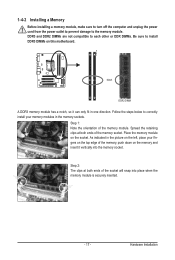
... to prevent hardware damage. • Memory modules have a foolproof design. Hardware Installation - 16 - When enabling Dual Channel mode with two memory modules, it is installed, the BIOS will double the original memory bandwidth. A memory module can be used . (Go to GIGABYTE's website for optimum performance. After the memory is recommended that memory of...
... to prevent hardware damage. • Memory modules have a foolproof design. Hardware Installation - 16 - When enabling Dual Channel mode with two memory modules, it is installed, the BIOS will double the original memory bandwidth. A memory module can be used . (Go to GIGABYTE's website for optimum performance. After the memory is recommended that memory of...
Manual
Page 17
...make sure to turn off the computer and unplug the power cord from the power outlet to prevent damage to correctly install your fingers on the memory and insert it can only fit in the memory sockets. Notch DDR3 DIMM A DDR3 ... your memory modules in one direction. DDR3 and DDR2 DIMMs are not compatible to each other or DDR DIMMs. Be sure to install DDR3 DIMMs on the socket. Step 1: Note the orientation of the memory, push down on the top edge of the memory... the socket will snap into the memory socket. Place the memory module on this motherboard. Hardware Installation
...make sure to turn off the computer and unplug the power cord from the power outlet to prevent damage to correctly install your fingers on the memory and insert it can only fit in the memory sockets. Notch DDR3 DIMM A DDR3 ... your memory modules in one direction. DDR3 and DDR2 DIMMs are not compatible to each other or DDR DIMMs. Be sure to install DDR3 DIMMs on the socket. Step 1: Note the orientation of the memory, push down on the top edge of the memory... the socket will snap into the memory socket. Place the memory module on this motherboard. Hardware Installation
Manual
Page 18
... on the top edge of the PCI Express slot to prevent hardware damage. If necessary, go to BIOS Setup to correctly install your expansion card(s). 7. Hardware Installation - 18 - Locate an expansion slot that came with a screw. 5. Remove the metal slot cover from the power outlet... before you begin to the chassis back panel with your computer. Example: Installing and Removing a PCI Express Graphics Card: • Installing a Graphics Card: Gently push down on your expansion card. • Always turn off the computer and unplug the ...
... on the top edge of the PCI Express slot to prevent hardware damage. If necessary, go to BIOS Setup to correctly install your expansion card(s). 7. Hardware Installation - 18 - Locate an expansion slot that came with a screw. 5. Remove the metal slot cover from the power outlet... before you begin to the chassis back panel with your computer. Example: Installing and Removing a PCI Express Graphics Card: • Installing a Graphics Card: Gently push down on your expansion card. • Always turn off the computer and unplug the ...
Manual
Page 19
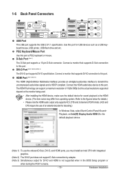
...formats. (AC3 and DTS require the use of 1920x1080p but the actual resolutions supported depend on the monitor being used. • After installing the HDMI device, make sure the default device for sound playback is not supported when in the BIOS Setup program or when during the ...supports a 15-pin D-Sub connector. Refer to the default playback device. (Note 1) To use the onboard D-Sub, DVI-D, and HDMI ports, you must install an Intel CPU with integrated graphics. (Note 2) The DVI-D port does not support D-Sub connection by adapter. (Note 3) Simultaneous output for USB devices such...
...formats. (AC3 and DTS require the use of 1920x1080p but the actual resolutions supported depend on the monitor being used. • After installing the HDMI device, make sure the default device for sound playback is not supported when in the BIOS Setup program or when during the ...supports a 15-pin D-Sub connector. Refer to the default playback device. (Note 1) To use the onboard D-Sub, DVI-D, and HDMI ports, you must install an Intel CPU with integrated graphics. (Note 2) The DVI-D port does not support D-Sub connection by adapter. (Note 3) Simultaneous output for USB devices such...
Manual
Page 20
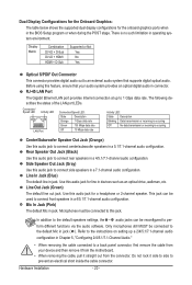
... to an external audio system that your device and then remove it from the connector. Use this feature, ensure that supports digital optical audio. Hardware Installation - 20 - Before using this audio jack for a headphone or 2-channel speaker. Connection/ Speed LED Activity LED LAN Port Connection/Speed LED: State Description Orange 1 Gbps...
... to an external audio system that your device and then remove it from the connector. Use this feature, ensure that supports digital optical audio. Hardware Installation - 20 - Before using this audio jack for a headphone or 2-channel speaker. Connection/ Speed LED Activity LED LAN Port Connection/Speed LED: State Description Orange 1 Gbps...
Manual
Page 21
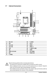
Unplug the power cord from the power outlet to prevent damage to the devices. • After installing the device and before connecting external devices: • First make sure the device cable has been securely attached to turn off the devices and your ... LED Read the following guidelines before turning on the computer, make sure your devices are compliant with the connectors you wish to connect. • Before installing the devices, be sure to the connector on the motherboard. - 21 - Hardware...
Unplug the power cord from the power outlet to prevent damage to the devices. • After installing the device and before connecting external devices: • First make sure the device cable has been securely attached to turn off the devices and your ... LED Read the following guidelines before turning on the computer, make sure your devices are compliant with the connectors you wish to connect. • Before installing the devices, be sure to the connector on the motherboard. - 21 - Hardware...
Manual
Page 22
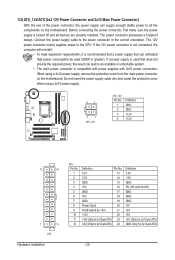
... a 2x12 power supply, remove the protective cover from the main power connector on the motherboard. Connect the power supply cable to all devices are properly installed. When using a 2x10 power supply. 42 31 ATX_12V ATX_12V: Pin No. 1 2 3 4 Definition GND GND +12V +12V 12 24 1 13 ATX Hardware... Installation ATX: Pin No. 1 2 3 4 5 6 7 8 9 10 11 12 Definition Pin No. 3.3V 13 3.3V 14 GND 15 +5V 16 GND 17 +5V 18 GND 19 Power Good ...
... a 2x12 power supply, remove the protective cover from the main power connector on the motherboard. Connect the power supply cable to all devices are properly installed. When using a 2x10 power supply. 42 31 ATX_12V ATX_12V: Pin No. 1 2 3 4 Definition GND GND +12V +12V 12 24 1 13 ATX Hardware... Installation ATX: Pin No. 1 2 3 4 5 6 7 8 9 10 11 12 Definition Pin No. 3.3V 13 3.3V 14 GND 15 +5V 16 GND 17 +5V 18 GND 19 Power Good ...
Manual
Page 23
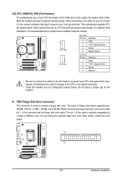
...blocks. The motherboard supports CPU fan speed control, which requires the use of the connector and the floppy disk drive cable. Hardware Installation Before connecting a floppy disk drive, be sure to prevent your CPU and system from overheating. For purchasing the optional floppy disk... drive cable, please contact the local dealer. 33 1 34 2 - 23 - The types of different color. When connecting a fan cable, be installed inside the chassis. 1 CPU_FAN 1 SYS_FAN CPU_FAN: Pin No. Definition 1 GND 2 +12V / Speed Control 3 Sense 4 Reserve • Be sure to ...
...blocks. The motherboard supports CPU fan speed control, which requires the use of the connector and the floppy disk drive cable. Hardware Installation Before connecting a floppy disk drive, be sure to prevent your CPU and system from overheating. For purchasing the optional floppy disk... drive cable, please contact the local dealer. 33 1 34 2 - 23 - The types of different color. When connecting a fan cable, be installed inside the chassis. 1 CPU_FAN 1 SYS_FAN CPU_FAN: Pin No. Definition 1 GND 2 +12V / Speed Control 3 Sense 4 Reserve • Be sure to ...
Manual
Page 24
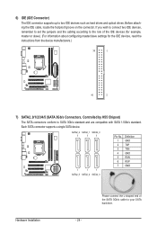
... cable, locate the foolproof groove on the connector. SATA2_2 SATA2_1 SATA2_0 7 7 7 1 1 1 SATA2_5 SATA2_4 SATA2_3 Pin No. 1 2 3 4 5 6 7 Definition GND TXP TXN GND RXN RXP GND Hardware Installation - 24 - Please connect the L-shaped end of the IDE devices (for example, master or slave). (For information about configuring master/slave settings for the IDE...
... cable, locate the foolproof groove on the connector. SATA2_2 SATA2_1 SATA2_0 7 7 7 1 1 1 SATA2_5 SATA2_4 SATA2_3 Pin No. 1 2 3 4 5 6 7 Definition GND TXP TXN GND RXN RXP GND Hardware Installation - 24 - Please connect the L-shaped end of the IDE devices (for example, master or slave). (For information about configuring master/slave settings for the IDE...


