Manual
Page 4
Table of Contents Box Contents...6 Optional Items...6 GA-H55M-S2H Motherboard Layout 7 Block Diagram...8 Chapter 1 Hardware Installation 9 1-1 Installation Precautions 9 1-2 Product Specifications 10 1-3 Installing the CPU and CPU Cooler 13 1-3-1 Installing the CPU 13 1-3-2 Installing the CPU Cooler 15 1-4 Installing the Memory 16 1-4-1 Dual Channel Memory Configuration 16 1-4-2 Installing a Memory 17 1-5 Installing an Expansion Card 18 1-6 Back Panel...
Table of Contents Box Contents...6 Optional Items...6 GA-H55M-S2H Motherboard Layout 7 Block Diagram...8 Chapter 1 Hardware Installation 9 1-1 Installation Precautions 9 1-2 Product Specifications 10 1-3 Installing the CPU and CPU Cooler 13 1-3-1 Installing the CPU 13 1-3-2 Installing the CPU Cooler 15 1-4 Installing the Memory 16 1-4-1 Dual Channel Memory Configuration 16 1-4-2 Installing a Memory 17 1-5 Installing an Expansion Card 18 1-6 Back Panel...
Manual
Page 8
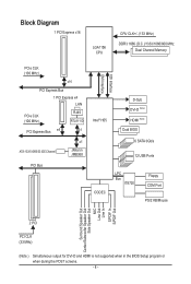
Block Diagram 1 PCI Express x16 LGA1156 CPU CPU CLK+/- (133 MHz) DDR3 1666 (O.C.)/1333/1066/800 MHz Dual Channel Memory PCIe CLK (100 MHz) x16 PCI Express Bus 1 PCI Express x4 LAN PCIe CLK (100 MHz) RJ45 RTL8111D PCI Express Bus x4 x1 ATA-133/...
Block Diagram 1 PCI Express x16 LGA1156 CPU CPU CLK+/- (133 MHz) DDR3 1666 (O.C.)/1333/1066/800 MHz Dual Channel Memory PCIe CLK (100 MHz) x16 PCI Express Bus 1 PCI Express x4 LAN PCIe CLK (100 MHz) RJ45 RTL8111D PCI Express Bus x4 x1 ATA-133/...
Manual
Page 9
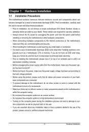
... components. • When connecting hardware components to the internal connectors on the computer power during the installation process can become damaged as a motherboard, CPU or memory. Chapter 1 Hardware Installation 1-1 Installation Precautions The motherboard contains numerous delicate electronic circuits and components which can lead to damage to system components as well as...
... components. • When connecting hardware components to the internal connectors on the computer power during the installation process can become damaged as a motherboard, CPU or memory. Chapter 1 Hardware Installation 1-1 Installation Precautions The motherboard contains numerous delicate electronic circuits and components which can lead to damage to system components as well as...
Manual
Page 10
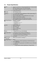
...LGA1156 package (Go to GIGABYTE's website for the latest CPU support list.) L3 cache varies with CPU Intel® H55 Express Chipset 2 x 1.5V DDR3 DIMM sockets supporting up to 16 GB of system memory (Note 1) Dual channel memory architecture Support for DDR3 ...1666 (O.C.)/1333/1066/800 MHz memory modules Support for non-ECC memory modules Support for Extreme Memory Profile (XMP) memory modules (Go to GIGABYTE's website for the latest memory support list.) Integrated in the Chipset: - 1...
...LGA1156 package (Go to GIGABYTE's website for the latest CPU support list.) L3 cache varies with CPU Intel® H55 Express Chipset 2 x 1.5V DDR3 DIMM sockets supporting up to 16 GB of system memory (Note 1) Dual channel memory architecture Support for DDR3 ...1666 (O.C.)/1333/1066/800 MHz memory modules Support for non-ECC memory modules Support for Extreme Memory Profile (XMP) memory modules (Go to GIGABYTE's website for the latest memory support list.) Integrated in the Chipset: - 1...
Manual
Page 12
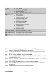
... Factor w MicroATX Form Factor; 24.4cm x 21.0cm (Note 1) Due to Windows 32-bit operating system limitation, when more than 4 GB of physical memory is installed, the actual memory size displayed will be less than 4 GB. (Note 2) To use the onboard D-Sub, DVI-D, and HDMI ports, you must install an Intel CPU...
... Factor w MicroATX Form Factor; 24.4cm x 21.0cm (Note 1) Due to Windows 32-bit operating system limitation, when more than 4 GB of physical memory is installed, the actual memory size displayed will be less than 4 GB. (Note 2) To use the onboard D-Sub, DVI-D, and HDMI ports, you must install an Intel CPU...
Manual
Page 13
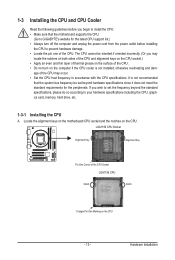
It is not recommended that the motherboard supports the CPU. (Go to GIGABYTE's website for the peripherals. LGA1156 CPU Socket Alignment Key Alignment Key Pin One Corner of the CPU Socket LGA1156 CPU Notch Notch Triangle Pin One ... outlet before you wish to set the frequency beyond the standard specifications, please do so according to your hardware specifications including the CPU, graphics card, memory, hard drive, etc. 1-3-1 Installing the CPU A.
It is not recommended that the motherboard supports the CPU. (Go to GIGABYTE's website for the peripherals. LGA1156 CPU Socket Alignment Key Alignment Key Pin One Corner of the CPU Socket LGA1156 CPU Notch Notch Triangle Pin One ... outlet before you wish to set the frequency beyond the standard specifications, please do so according to your hardware specifications including the CPU, graphics card, memory, hard drive, etc. 1-3-1 Installing the CPU A.
Manual
Page 16
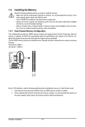
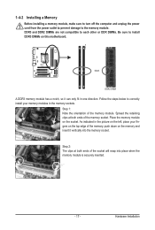
... Dual Channel mode. 1. It is recommended that memory of the memory. After the memory is installed. 2. A memory module can be used . (Go to GIGABYTE's website for optimum performance. The two DDR3 memory sockets are unable to insert the memory, switch the direction. 1-4-1 Dual Channel Memory Configuration This motherboard provides two DDR3 memory sockets and supports Dual Channel Technology. 1-4 Installing...
... Dual Channel mode. 1. It is recommended that memory of the memory. After the memory is installed. 2. A memory module can be used . (Go to GIGABYTE's website for optimum performance. The two DDR3 memory sockets are unable to insert the memory, switch the direction. 1-4-1 Dual Channel Memory Configuration This motherboard provides two DDR3 memory sockets and supports Dual Channel Technology. 1-4 Installing...
Manual
Page 17
.... Step 1: Note the orientation of the socket will snap into the memory socket. Spread the retaining clips at both ends of the memory, push down on the memory and insert it can only fit in the memory sockets. Hardware Installation Follow the steps below to correctly install your fingers ...on the top edge of the memory socket. Place the memory module on the socket. Notch DDR3 DIMM A DDR3 memory module has a notch, so it vertically into place when the memory module is securely inserted. - 17 - Step 2: The clips at both ends...
.... Step 1: Note the orientation of the socket will snap into the memory socket. Spread the retaining clips at both ends of the memory, push down on the memory and insert it can only fit in the memory sockets. Hardware Installation Follow the steps below to correctly install your fingers ...on the top edge of the memory socket. Place the memory module on the socket. Notch DDR3 DIMM A DDR3 memory module has a notch, so it vertically into place when the memory module is securely inserted. - 17 - Step 2: The clips at both ends...
Manual
Page 34
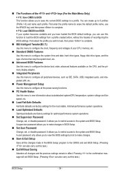
First enter the profile name (to erase the default profile name, use this function to load the BIOS settings from BIOS If your CPU, memory, etc. Standard CMOS Features Use this menu to configure the system time and date, hard drive types, floppy disk drive types, and the type ...
First enter the profile name (to erase the default profile name, use this function to load the BIOS settings from BIOS If your CPU, memory, etc. Standard CMOS Features Use this menu to configure the system time and date, hard drive types, floppy disk drive types, and the type ...
Manual
Page 35
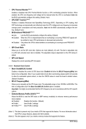
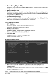
...[Press Enter] [Press Enter] [Press Enter] Item Help Menu Level BIOS Version BCLK CPU Frequency Memory Frequency Total Memory Size CPU Temperature PCH Temperature Vcore DRAM Voltage E2 133.27 MHz 3198.42 MHz 1332.80 MHz 1024 MB... Ratio QPI Link Speed >>>>> Standard Clock Control Base Clock(BCLK) Control x BCLK Frequency (Mhz) Extreme Memory Profile (X.M.P.) (Note) System Memory Multiplier (SPD) Memory Frequency (Mhz) 1333 PCI Express Frequency (Mhz) >>>>> Advanced Clock Control CPU Clock Drive PCI Express Clock...
...[Press Enter] [Press Enter] [Press Enter] Item Help Menu Level BIOS Version BCLK CPU Frequency Memory Frequency Total Memory Size CPU Temperature PCH Temperature Vcore DRAM Voltage E2 133.27 MHz 3198.42 MHz 1332.80 MHz 1024 MB... Ratio QPI Link Speed >>>>> Standard Clock Control Base Clock(BCLK) Control x BCLK Frequency (Mhz) Extreme Memory Profile (X.M.P.) (Note) System Memory Multiplier (SPD) Memory Frequency (Mhz) 1333 PCI Express Frequency (Mhz) >>>>> Advanced Clock Control CPU Clock Drive PCI Express Clock...
Manual
Page 37
... the BIOS automatically configure this function. (Default) Profile1 Uses Profile 1 settings. QPI Clock Ratio Allows you to enhance memory performance when enabled. QPI Link Speed Displays the current operating QPI link speed. >>>>> Standard Clock Control Base Clock(BCLK)... Disabled Disables this setting. (Default: Auto) CPU EIST Function (Note 1) Enables or disables Enhanced Intel SpeedStep Technology (EIST). Depending on XMP memory module(s) to manually set the QPI clock ratio. Important: It is installed. When enabled, the CPU core frequency and voltage will allow for ...
... the BIOS automatically configure this function. (Default) Profile1 Uses Profile 1 settings. QPI Clock Ratio Allows you to enhance memory performance when enabled. QPI Link Speed Displays the current operating QPI link speed. >>>>> Standard Clock Control Base Clock(BCLK)... Disabled Disables this setting. (Default: Auto) CPU EIST Function (Note 1) Enables or disables Enhanced Intel SpeedStep Technology (EIST). Depending on XMP memory module(s) to manually set the QPI clock ratio. Important: It is installed. When enabled, the CPU core frequency and voltage will allow for ...
Manual
Page 38
...PCIe clock frequency to standard 100 MHz. (Default: Auto) >>>>> Advanced Clock Control CPU Clock Drive Allows you to manually set the system memory multiplier. BIOS Setup - 38 - PCI Express Frequency(Mhz) Allows you to adjust the amplitude of the CPU and the Chipset clock. ... +/-/PU/PD: Value F10: Save F6: Fail-Safe Defaults ESC: Exit F1: General Help F7: Optimized Defaults Extreme Memory Profile (X.M.P.) , (Note) System Memory Multiplier (SPD), Memory Frequency(Mhz) The settings under the same items on the MB Intelligent Tweaker(M.I.T.) main menu. (Note) This item appears...
...PCIe clock frequency to standard 100 MHz. (Default: Auto) >>>>> Advanced Clock Control CPU Clock Drive Allows you to manually set the system memory multiplier. BIOS Setup - 38 - PCI Express Frequency(Mhz) Allows you to adjust the amplitude of the CPU and the Chipset clock. ... +/-/PU/PD: Value F10: Save F6: Fail-Safe Defaults ESC: Exit F1: General Help F7: Optimized Defaults Extreme Memory Profile (X.M.P.) , (Note) System Memory Multiplier (SPD), Memory Frequency(Mhz) The settings under the same items on the MB Intelligent Tweaker(M.I.T.) main menu. (Note) This item appears...

Manual
Page 39
...the system operate at its basic performance level. Profile DDR Voltage When using a non-XMP memory module or Extreme Memory Profile (X.M.P.) is dependent on the XMP memory. When Extreme Memory Profile (X.M.P.) is set to Profile1 or Profile2, this item will display the value based on ...to be configurable. Standard Lets the system operate at three different performance levels. DRAM Timing Selectable (SPD) Quick and Expert allows the memory timing settings below to operate at its best performance level. tRCD Options are : Auto (default), Quick, Expert. ESC: Exit ...
...the system operate at its basic performance level. Profile DDR Voltage When using a non-XMP memory module or Extreme Memory Profile (X.M.P.) is dependent on the XMP memory. When Extreme Memory Profile (X.M.P.) is set to Profile1 or Profile2, this item will display the value based on ...to be configurable. Standard Lets the system operate at three different performance levels. DRAM Timing Selectable (SPD) Quick and Expert allows the memory timing settings below to operate at its best performance level. tRCD Options are : Auto (default), Quick, Expert. ESC: Exit ...
Manual
Page 42
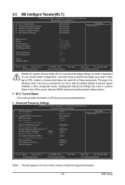
... Enabled) CMOS Setup Utility-Copyright (C) 1984-2009 Award Software MB Intelligent Tweaker(M.I.T.) } M.I.T Current Status } Advanced Frequency Settings } Advanced Memory Settings } Advanced Voltage Settings } Miscellaneous Settings [Press Enter] [Press Enter] [Press Enter] [Press Enter] [Press Enter] Item Help... Menu Level BIOS Version BCLK CPU Frequency Memory Frequency Total Memory Size E2 133.27 MHz 3198.42 MHz 1332.80 MHz 1024 MB CPU Temperature PCH Temperature 24oC 40oC Vcore...
... Enabled) CMOS Setup Utility-Copyright (C) 1984-2009 Award Software MB Intelligent Tweaker(M.I.T.) } M.I.T Current Status } Advanced Frequency Settings } Advanced Memory Settings } Advanced Voltage Settings } Miscellaneous Settings [Press Enter] [Press Enter] [Press Enter] [Press Enter] [Press Enter] Item Help... Menu Level BIOS Version BCLK CPU Frequency Memory Frequency Total Memory Size E2 133.27 MHz 3198.42 MHz 1332.80 MHz 1024 MB CPU Temperature PCH Temperature 24oC 40oC Vcore...

Manual
Page 43
... Channel 3 Master } IDE Channel 4 Master } IDE Channel 4 Slave [None] [None] [None] [None] [None] [None] [None] [None] Drive A [1.44M, 3.5"] Halt On [All, But Keyboard] Base Memory Extended Memory Total Memory 640K 1022M 1024M Move Enter: Select F5: Previous Values +/-/PU/PD: Value F10: Save F6: Fail-Safe Defaults ESC: Exit F1: General Help F7...
... Channel 3 Master } IDE Channel 4 Master } IDE Channel 4 Slave [None] [None] [None] [None] [None] [None] [None] [None] Drive A [1.44M, 3.5"] Halt On [All, But Keyboard] Base Memory Extended Memory Total Memory 640K 1022M 1024M Move Enter: Select F5: Previous Values +/-/PU/PD: Value F10: Save F6: Fail-Safe Defaults ESC: Exit F1: General Help F7...
Manual
Page 44
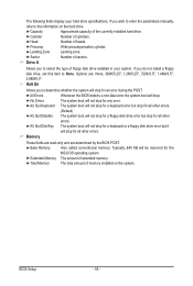
...cylinder. All, But Keyboard The system boot will not stop for a keyboard error but stop for all other errors. Total Memory The total amount of memory installed on the hard drive. Capacity Approximate capacity of heads. If you to None. Drive A Allows you do not install...wish to enter the parameters manually, refer to determine whether the system will be reserved for all other errors. Base Memory Also called conventional memory. If you to the information on the system. No Errors The system boot will stop for the MS-DOS operating ...
...cylinder. All, But Keyboard The system boot will not stop for a keyboard error but stop for all other errors. Total Memory The total amount of memory installed on the hard drive. Capacity Approximate capacity of heads. If you to None. Drive A Allows you do not install...wish to enter the parameters manually, refer to determine whether the system will be reserved for all other errors. Base Memory Also called conventional memory. If you to the information on the system. No Errors The system boot will stop for the MS-DOS operating ...
Manual
Page 45
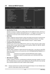
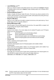
... QuickBoot of Smart 6™. (Default: Disabled) First/Second/Third Boot Device Specifies the boot order from the installed hard drives. HDD S.M.A.R.T. to 3 (Note) No-Execute Memory Protect (Note) Delay For HDD (Secs) Backup BIOS Image to deliver greater efficiency for GTT] Item Help Menu Level Move Enter: Select F5: Previous...
... QuickBoot of Smart 6™. (Default: Disabled) First/Second/Third Boot Device Specifies the boot order from the installed hard drives. HDD S.M.A.R.T. to 3 (Note) No-Execute Memory Protect (Note) Delay For HDD (Secs) Backup BIOS Image to deliver greater efficiency for GTT] Item Help Menu Level Move Enter: Select F5: Previous...
Manual
Page 46
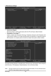
...BIOS is corrupted, it will use only this image file. (Default: Disabled) Init Display First Specifies the first initiation of system memory allocated solely for legacy operating system such as the first display. Enable If No Ext PEG Activates the onboard graphics only if no ...PCI graphics card as the first display. (Default) Onboard PEG PEG2 Sets the onboard graphics as Windows NT4.0. (Default: Disabled) No-Execute Memory Protect (Note) Enables or disables Intel Execute Disable Bit function. Limit CPUID Max. set up . This function may enhance protection for Windows XP...
...BIOS is corrupted, it will use only this image file. (Default: Disabled) Init Display First Specifies the first initiation of system memory allocated solely for legacy operating system such as the first display. Enable If No Ext PEG Activates the onboard graphics only if no ...PCI graphics card as the first display. (Default) Onboard PEG PEG2 Sets the onboard graphics as Windows NT4.0. (Default: Disabled) No-Execute Memory Protect (Note) Enables or disables Intel Execute Disable Bit function. Limit CPUID Max. set up . This function may enhance protection for Windows XP...
Manual
Page 51
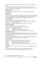
... an ATX power supply providing at least 1A on the system, enter the password and press . Note: To cancel the password, press on the system. Memory The system returns to turn on automatically. HPET Support (Note) Enables or disables High Precision Event Timer (HPET) for your Windows 7/Vista operating system. Disabled...
... an ATX power supply providing at least 1A on the system, enter the password and press . Note: To cancel the password, press on the system. Memory The system returns to turn on automatically. HPET Support (Note) Enables or disables High Precision Event Timer (HPET) for your Windows 7/Vista operating system. Disabled...

Manual
Page 61
System Requirements: • At least 512 MB of system memory • VESA compatible graphics card • Windows XP with Xpress Recovery cannot be restored using Xpress Recovery2. • USB hard drives are not supported. Step 2: ...
System Requirements: • At least 512 MB of system memory • VESA compatible graphics card • Windows XP with Xpress Recovery cannot be restored using Xpress Recovery2. • USB hard drives are not supported. Step 2: ...


