Manual
Page 1
GA-H55M-S2H LGA1156 socket motherboard for Intel® Core™ i7 processor family/ Intel® Core™ i5 processor family/ Intel® Core™ i3 processor family User's Manual Rev. 1001 12ME-H55MS2H-1001R
GA-H55M-S2H LGA1156 socket motherboard for Intel® Core™ i7 processor family/ Intel® Core™ i5 processor family/ Intel® Core™ i3 processor family User's Manual Rev. 1001 12ME-H55MS2H-1001R
Manual
Page 2
Motherboard GA-H55M-S2H Dec. 7, 2009 Motherboard GA-H55M-S2H Dec. 7, 2009
Motherboard GA-H55M-S2H Dec. 7, 2009 Motherboard GA-H55M-S2H Dec. 7, 2009
Manual
Page 3
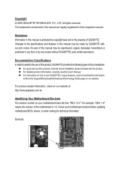
...the Support&Downloads\Motherboard\Technology Guide page on our website. For product-related information, check on our website at: http://www.gigabyte.com.tw Identifying Your Motherboard Revision The revision number on how to assist in any form or by any means without prior ...reproduced, copied, translated, transmitted, or published in the use GIGABYTE's unique features, read the User's Manual. Check your motherboard looks like this product, GIGABYTE provides the following types of documentations: For quick set-up of GIGABYTE. No part of the motherboard is the property of the...
...the Support&Downloads\Motherboard\Technology Guide page on our website. For product-related information, check on our website at: http://www.gigabyte.com.tw Identifying Your Motherboard Revision The revision number on how to assist in any form or by any means without prior ...reproduced, copied, translated, transmitted, or published in the use GIGABYTE's unique features, read the User's Manual. Check your motherboard looks like this product, GIGABYTE provides the following types of documentations: For quick set-up of GIGABYTE. No part of the motherboard is the property of the...
Manual
Page 4
Table of Contents Box Contents...6 Optional Items...6 GA-H55M-S2H Motherboard Layout 7 Block Diagram...8 Chapter 1 Hardware Installation 9 1-1 Installation Precautions 9 1-2 Product Specifications 10 1-3 Installing the CPU and CPU Cooler 13 1-3-1 Installing the CPU 13 1-3-2 Installing the ...
Table of Contents Box Contents...6 Optional Items...6 GA-H55M-S2H Motherboard Layout 7 Block Diagram...8 Chapter 1 Hardware Installation 9 1-1 Installation Precautions 9 1-2 Product Specifications 10 1-3 Installing the CPU and CPU Cooler 13 1-3-1 Installing the CPU 13 1-3-2 Installing the ...
Manual
Page 5
Chapter 3 Drivers Installation 57 3-1 Installing Chipset Drivers 57 3-2 Application Software 58 3-3 Technical Manuals 58 3-4 Contact...59 3-5 System...59 3-6 Download Center 60 3-7 New Utilities...60 Chapter 4 Unique Features 61 4-1 Xpress Recovery2 61 4-2 BIOS Update Utilities 64 4-2-1 Updating the BIOS with the Q-Flash Utility 64 4-2-2 Updating the BIOS with the @BIOS Utility 67 4-3 EasyTune 6...68 4-4 Dynamic Energy Saver™ 2 69 4-5 Q-Share...71 4-6 Smart 6™...72 4-7 Auto Green...75 Chapter 5 Appendix...77 5-1 Configuring Audio Input and Output 77 5-1-1 Configuring ...
Chapter 3 Drivers Installation 57 3-1 Installing Chipset Drivers 57 3-2 Application Software 58 3-3 Technical Manuals 58 3-4 Contact...59 3-5 System...59 3-6 Download Center 60 3-7 New Utilities...60 Chapter 4 Unique Features 61 4-1 Xpress Recovery2 61 4-2 BIOS Update Utilities 64 4-2-1 Updating the BIOS with the Q-Flash Utility 64 4-2-2 Updating the BIOS with the @BIOS Utility 67 4-3 EasyTune 6...68 4-4 Dynamic Energy Saver™ 2 69 4-5 Q-Share...71 4-6 Smart 6™...72 4-7 Auto Green...75 Chapter 5 Appendix...77 5-1 Configuring Audio Input and Output 77 5-1-1 Configuring ...
Manual
Page 6
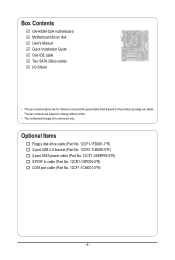
...-1UB030-5*R) 2-port SATA power cable (Part No. 12CF1-2SERPW-0*R) S/PDIF In cable (Part No. 12CR1-1SPDIN-0*R) COM port cable (Part No. 12CF1-1CM001-3*R) - 6 - Box Contents GA-H55M-S2H motherboard Motherboard driver disk User's Manual Quick Installation Guide One IDE cable Two SATA 3Gb/s cables I/O Shield • The box contents above are subject to...
...-1UB030-5*R) 2-port SATA power cable (Part No. 12CF1-2SERPW-0*R) S/PDIF In cable (Part No. 12CR1-1SPDIN-0*R) COM port cable (Part No. 12CF1-1CM001-3*R) - 6 - Box Contents GA-H55M-S2H motherboard Motherboard driver disk User's Manual Quick Installation Guide One IDE cable Two SATA 3Gb/s cables I/O Shield • The box contents above are subject to...
Manual
Page 7
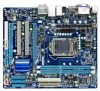
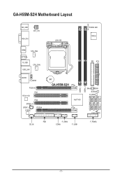
GA-H55M-S2H Motherboard Layout KB_USB ATX_12V VGA_DVI LGA1156 PHASE LED IT8720 HDMI SYS_FAN OPTICAL R_USB USB_LAN CPU_FAN AUDIO F_AUDIO PCIEX16 PCI1 RTL8111D PCI2 SPDIF_O SPDIF_I CODEC PCIEX4 IDE ATX BAT GA-H55M-S2H Intel® H55 JMicron JMB368 M_BIOS B_BIOS CLR_CMOS FDD CD_IN F_USB2 COMA F_USB1 F_PANEL DDR3_1 DDR3_2 SATA2_5 SATA2_2 SATA2_4 SATA2_1 SATA2_3 SATA2_0 - 7 -
GA-H55M-S2H Motherboard Layout KB_USB ATX_12V VGA_DVI LGA1156 PHASE LED IT8720 HDMI SYS_FAN OPTICAL R_USB USB_LAN CPU_FAN AUDIO F_AUDIO PCIEX16 PCI1 RTL8111D PCI2 SPDIF_O SPDIF_I CODEC PCIEX4 IDE ATX BAT GA-H55M-S2H Intel® H55 JMicron JMB368 M_BIOS B_BIOS CLR_CMOS FDD CD_IN F_USB2 COMA F_USB1 F_PANEL DDR3_1 DDR3_2 SATA2_5 SATA2_2 SATA2_4 SATA2_1 SATA2_3 SATA2_0 - 7 -
Manual
Page 8
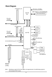
Block Diagram 1 PCI Express x16 LGA1156 CPU CPU CLK+/- (133 MHz) DDR3 1666 (O.C.)/1333/1066/800 MHz Dual Channel Memory PCIe CLK (100 MHz) x16 PCI Express Bus 1 PCI Express x4 LAN PCIe CLK (100 MHz) RJ45 RTL8111D PCI Express Bus x4 x1 ATA-133/100/66/33 IDE Channel x1 JMicron JMB368 PCI Bus Intel® H55 CODEC FDI Interface DMI Interface D-Sub DVI-D (Note) HDMI (Note) Dual BIOS 6 SATA 3Gb/s 12 USB Ports LPC Bus IT8720 Floppy COM Port PS/2 KB/Mouse Surround Speaker Out Center/Subwoofer Speaker Out Side Speaker Out MIC Line Out Line In S/PDIF In S/PDIF Out 2 PCI PCI CLK (33 ...
Block Diagram 1 PCI Express x16 LGA1156 CPU CPU CLK+/- (133 MHz) DDR3 1666 (O.C.)/1333/1066/800 MHz Dual Channel Memory PCIe CLK (100 MHz) x16 PCI Express Bus 1 PCI Express x4 LAN PCIe CLK (100 MHz) RJ45 RTL8111D PCI Express Bus x4 x1 ATA-133/100/66/33 IDE Channel x1 JMicron JMB368 PCI Bus Intel® H55 CODEC FDI Interface DMI Interface D-Sub DVI-D (Note) HDMI (Note) Dual BIOS 6 SATA 3Gb/s 12 USB Ports LPC Bus IT8720 Floppy COM Port PS/2 KB/Mouse Surround Speaker Out Center/Subwoofer Speaker Out Side Speaker Out MIC Line Out Line In S/PDIF In S/PDIF Out 2 PCI PCI CLK (33 ...
Manual
Page 9
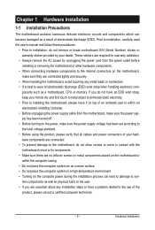
Hardware Installation ponents such as a motherboard, CPU or memory. If you are connected tightly and securely. • When handling the motherboard, avoid touching any installation steps or have it on top of an antistatic pad or within the computer casing. • Do not place the computer system on an uneven surface. • Do not place the computer system in contact with the motherboard circuit or its components. • Make sure there are no leftover screws or metal components placed on the motherboard or within an electrostatic shielding container. • Before unplugging ...
Hardware Installation ponents such as a motherboard, CPU or memory. If you are connected tightly and securely. • When handling the motherboard, avoid touching any installation steps or have it on top of an antistatic pad or within the computer casing. • Do not place the computer system on an uneven surface. • Do not place the computer system in contact with the motherboard circuit or its components. • Make sure there are no leftover screws or metal components placed on the motherboard or within an electrostatic shielding container. • Before unplugging ...
Manual
Page 10
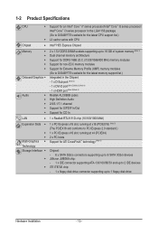
...i7 series processor/Intel® Core™ i5 series processor/ Intel® Core™ i3 series processor in the LGA1156 package (Go to GIGABYTE's website for the latest CPU support list.) L3 cache varies with CPU Intel® H55 Express Chipset 2 x 1.5V DDR3 DIMM sockets ... for DDR3 1666 (O.C.)/1333/1066/800 MHz memory modules Support for non-ECC memory modules Support for Extreme Memory Profile (XMP) memory modules (Go to GIGABYTE's website for the latest memory support list.) Integrated in the Chipset: - 1 x D-Sub port (Note 2) - 1 x DVI-D port (Note 2)(Note 3) (Note 4) - 1 x HDMI ...
...i7 series processor/Intel® Core™ i5 series processor/ Intel® Core™ i3 series processor in the LGA1156 package (Go to GIGABYTE's website for the latest CPU support list.) L3 cache varies with CPU Intel® H55 Express Chipset 2 x 1.5V DDR3 DIMM sockets ... for DDR3 1666 (O.C.)/1333/1066/800 MHz memory modules Support for non-ECC memory modules Support for Extreme Memory Profile (XMP) memory modules (Go to GIGABYTE's website for the latest memory support list.) Integrated in the Chipset: - 1 x D-Sub port (Note 2) - 1 x DVI-D port (Note 2)(Note 3) (Note 4) - 1 x HDMI ...

Manual
Page 11
Hardware Installation Up to 12 USB 2.0/1.1 ports (8 on the back panel, 4 via the USB brackets connected to the internal USB headers) Internal w 1 x 24-pin ATX main power connector Connectors w 1 x 4-pin ATX 12V power connector w 1 x floppy disk drive connector w 1 x IDE connector w 6 x SATA 3Gb/s connectors w 1 x CPU fan header w 1 x system fan header w 1 x front panel header w 1 x front panel audio header w 1 x CD In connector w 1 x S/PDIF In header w 1 x S/PDIF Out header w 2 x USB 2.0/1.1 headers...
Hardware Installation Up to 12 USB 2.0/1.1 ports (8 on the back panel, 4 via the USB brackets connected to the internal USB headers) Internal w 1 x 24-pin ATX main power connector Connectors w 1 x 4-pin ATX 12V power connector w 1 x floppy disk drive connector w 1 x IDE connector w 6 x SATA 3Gb/s connectors w 1 x CPU fan header w 1 x system fan header w 1 x front panel header w 1 x front panel audio header w 1 x CD In connector w 1 x S/PDIF In header w 1 x S/PDIF Out header w 2 x USB 2.0/1.1 headers...
Manual
Page 12
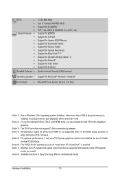
BIOS w w w w Unique Features w w w w w w w w w w w Bundled Software w 2 x 64 Mbit flash Use of licensed AWARD BIOS Support for DualBIOS™ PnP 1.0a, DMI 2.0, SM BIOS 2.4, ACPI 1.0b Support for @BIOS Support for Q-Flash Support for Xpress BIOS Rescue Support for Download Center Support for Xpress Install Support for Xpress Recovery2 Support for EasyTune (Note 8) Support for Dynamic Energy Saver™ 2 Support for Smart 6™ Support for Auto Green Support for Q-Share Norton Internet ...
BIOS w w w w Unique Features w w w w w w w w w w w Bundled Software w 2 x 64 Mbit flash Use of licensed AWARD BIOS Support for DualBIOS™ PnP 1.0a, DMI 2.0, SM BIOS 2.4, ACPI 1.0b Support for @BIOS Support for Q-Flash Support for Xpress BIOS Rescue Support for Download Center Support for Xpress Install Support for Xpress Recovery2 Support for EasyTune (Note 8) Support for Dynamic Energy Saver™ 2 Support for Smart 6™ Support for Auto Green Support for Q-Share Norton Internet ...
Manual
Page 13
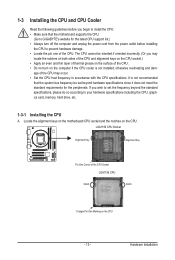
... CPU Notch Notch Triangle Pin One Marking on the computer if the CPU cooler is not recommended that the motherboard supports the CPU. (Go to GIGABYTE's website for the peripherals. The CPU cannot be set the frequency beyond hardware specifications since it does not meet the standard requirements for the latest...
... CPU Notch Notch Triangle Pin One Marking on the computer if the CPU cooler is not recommended that the motherboard supports the CPU. (Go to GIGABYTE's website for the peripherals. The CPU cannot be set the frequency beyond hardware specifications since it does not meet the standard requirements for the latest...
Manual
Page 14
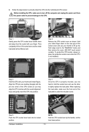
Then completely lift the CPU socket lever and the metal load plate will be lifted as shown. Align the CPU pin one marking (triangle) with the pin one hand to hold the socket lever and use the other to lightly replace the load plate. Step 1: Gently press the CPU socket lever handle down on the rear grip of the socket cover and use one corner of the load plate is under the shoulder screw. Step 4: Once the CPU is not installed.) Step 3: Hold the CPU with your index finger down and away from the power outlet to prevent damage to correctly install the CPU into its ...
Then completely lift the CPU socket lever and the metal load plate will be lifted as shown. Align the CPU pin one marking (triangle) with the pin one hand to hold the socket lever and use the other to lightly replace the load plate. Step 1: Gently press the CPU socket lever handle down on the rear grip of the socket cover and use one corner of the load plate is under the shoulder screw. Step 4: Once the CPU is not installed.) Step 3: Hold the CPU with your index finger down and away from the power outlet to prevent damage to correctly install the CPU into its ...
Manual
Page 15
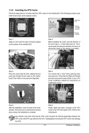
Step 4: You should hear a "click" when pushing down on installing the cooler.) Step 5: After the installation, check the back of the motherboard. Step 6: Finally, attach the power connector of the CPU cooler to your CPU cooler installation manual for instructions on the push pins diagonally. Check that the Male and Female push pins are joined closely. (Refer to the CPU fan header (CPU_FAN) on the motherboard. Use extreme care when removing the CPU cooler because the thermal grease/tape between the CPU cooler and CPU may damage the CPU. - 15 - If the push pin is inserted as...
Step 4: You should hear a "click" when pushing down on installing the cooler.) Step 5: After the installation, check the back of the motherboard. Step 6: Finally, attach the power connector of the CPU cooler to your CPU cooler installation manual for instructions on the push pins diagonally. Check that the Male and Female push pins are joined closely. (Refer to the CPU fan header (CPU_FAN) on the motherboard. Use extreme care when removing the CPU cooler because the thermal grease/tape between the CPU cooler and CPU may damage the CPU. - 15 - If the push pin is inserted as...
Manual
Page 16
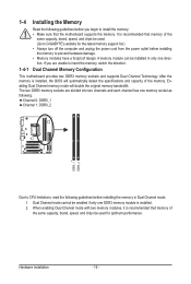
... original memory bandwidth. Hardware Installation - 16 - After the memory is recommended that memory of the same capacity, brand, speed, and chips be used . (Go to GIGABYTE's website for optimum performance. A memory module can be used for the latest memory support list.) • Always turn off the computer and unplug the power...
... original memory bandwidth. Hardware Installation - 16 - After the memory is recommended that memory of the same capacity, brand, speed, and chips be used . (Go to GIGABYTE's website for optimum performance. A memory module can be used for the latest memory support list.) • Always turn off the computer and unplug the power...
Manual
Page 17
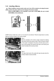
1-4-2 Installing a Memory Before installing a memory module, make sure to turn off the computer and unplug the power cord from the power outlet to prevent damage to install DDR3 DIMMs on this motherboard. Notch DDR3 DIMM A DDR3 memory module has a notch, so it vertically into place when the memory module is securely inserted. - 17 - Hardware Installation Place the memory module on the left, place your memory modules in one direction. Step 2: The clips at both ends of the memory, push down on the top edge of the socket will snap into the memory socket. Follow the steps ...
1-4-2 Installing a Memory Before installing a memory module, make sure to turn off the computer and unplug the power cord from the power outlet to prevent damage to install DDR3 DIMMs on this motherboard. Notch DDR3 DIMM A DDR3 memory module has a notch, so it vertically into place when the memory module is securely inserted. - 17 - Hardware Installation Place the memory module on the left, place your memory modules in one direction. Step 2: The clips at both ends of the memory, push down on the top edge of the socket will snap into the memory socket. Follow the steps ...
Manual
Page 18
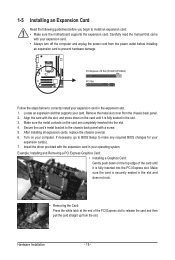
1-5 Installing an Expansion Card Read the following guidelines before installing an expansion card to make any required BIOS changes for your computer. Align the card with a screw. 5. Example: Installing and Removing a PCI Express Graphics Card: • Installing a Graphics Card: Gently push down on the card are completely inserted into the PCI Express slot. PCI Express x16 Slot (PCIEX16/PCIEX4) PCI Slot Follow the steps below to install an expansion card: • Make sure the motherboard supports the expansion card. Make sure the metal contacts on the card until it is ...
1-5 Installing an Expansion Card Read the following guidelines before installing an expansion card to make any required BIOS changes for your computer. Align the card with a screw. 5. Example: Installing and Removing a PCI Express Graphics Card: • Installing a Graphics Card: Gently push down on the card are completely inserted into the PCI Express slot. PCI Express x16 Slot (PCIEX16/PCIEX4) PCI Slot Follow the steps below to install an expansion card: • Make sure the motherboard supports the expansion card. Make sure the metal contacts on the card until it is ...
Manual
Page 19
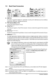
1-6 Back Panel Connectors (Note 1) (Note 1)(Note 2)(Note 3) (Note 1)(Note 3) USB Port The USB port supports the USB 2.0/1.1 specification. The HDMI Technology can support a maximum resolution of an external decoder for decoding.) In Windows Vista, select Start>Control Panel>Sound> Playback, set Intel(R) Display Audio HDMI 2 to the figures below for details.) • Please note the HDMI audio output only supports AC3, DTS and 2-channel-LPCM formats. (AC3 and DTS require the use the onboard D-Sub, DVI-D, and HDMI ports, you must install an Intel CPU with integrated graphics. (Note...
1-6 Back Panel Connectors (Note 1) (Note 1)(Note 2)(Note 3) (Note 1)(Note 3) USB Port The USB port supports the USB 2.0/1.1 specification. The HDMI Technology can support a maximum resolution of an external decoder for decoding.) In Windows Vista, select Start>Control Panel>Sound> Playback, set Intel(R) Display Audio HDMI 2 to the figures below for details.) • Please note the HDMI audio output only supports AC3, DTS and 2-channel-LPCM formats. (AC3 and DTS require the use the onboard D-Sub, DVI-D, and HDMI ports, you must install an Intel CPU with integrated graphics. (Note...
Manual
Page 20
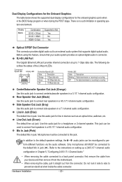
There is occurring Center/Subwoofer Speaker Out Jack (Orange) Use this audio jack to 1 Gbps data rate. Rear Speaker Out Jack (Black) Use this feature, ensure that supports digital optical audio. Refer to the instructions on setting up to connect center/subwoofer speakers in a 7.1-channel audio configuration. Hardware Installation - 20 - Before using this audio jack to the default Mic in the BIOS Setup program or when during the POST stage. The following describes the states of the LAN port LEDs. Line In Jack (Blue) The default line in a 4/5.1/7.1-channel audio ...
There is occurring Center/Subwoofer Speaker Out Jack (Orange) Use this audio jack to 1 Gbps data rate. Rear Speaker Out Jack (Black) Use this feature, ensure that supports digital optical audio. Refer to the instructions on setting up to connect center/subwoofer speakers in a 7.1-channel audio configuration. Hardware Installation - 20 - Before using this audio jack to the default Mic in the BIOS Setup program or when during the POST stage. The following describes the states of the LAN port LEDs. Line In Jack (Blue) The default line in a 4/5.1/7.1-channel audio ...
