Service Manual
Page 1
...trade names may be used in this document is strictly forbidden. Dell™ Latitude™ E6400 and E6400 ATG and Mobile Workstation Precision™ M2400 Service Manual Troubleshooting Working on Your Computer Base Assembly Hinge Covers Hard Drive WLAN/WiMax... Card WWAN Card WPAN (UWB/BT) Card FCM Fan Processor Heatsink Assembly Processor Module Memory Coin-Cell Battery Modular Drive LED Cover Keyboard...
...trade names may be used in this document is strictly forbidden. Dell™ Latitude™ E6400 and E6400 ATG and Mobile Workstation Precision™ M2400 Service Manual Troubleshooting Working on Your Computer Base Assembly Hinge Covers Hard Drive WLAN/WiMax... Card WWAN Card WPAN (UWB/BT) Card FCM Fan Processor Heatsink Assembly Processor Module Memory Coin-Cell Battery Modular Drive LED Cover Keyboard...
Service Manual
Page 2
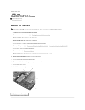
...the Card Cage). 12. Remove the bottom of the Base Assembly). 3. Remove the keyboard (see Removing the Bottom of the base assembly (see Removing the Keyboard). 9. Follow the instructions in Before Working on Your Computer. 2. Disconnect the 1394 cable from the system board, and unroute the...it. 1 1394 cable connector 2 system board 3 M2 x 3 screws (2) 4 1394 card Back to Contents Page 1394 Card Dell™ Latitude™ E6400 and E6400 ATG and Mobile Workstation Precision™ M2400 Service Manual Removing the 1394 Card Replacing the 1394 Card Removing the 1394 Card CAUTION: ...
...the Card Cage). 12. Remove the bottom of the Base Assembly). 3. Remove the keyboard (see Removing the Bottom of the base assembly (see Removing the Keyboard). 9. Follow the instructions in Before Working on Your Computer. 2. Disconnect the 1394 cable from the system board, and unroute the...it. 1 1394 cable connector 2 system board 3 M2 x 3 screws (2) 4 1394 card Back to Contents Page 1394 Card Dell™ Latitude™ E6400 and E6400 ATG and Mobile Workstation Precision™ M2400 Service Manual Removing the 1394 Card Replacing the 1394 Card Removing the 1394 Card CAUTION: ...
Service Manual
Page 3
...the two M2 x 3 screws. 3. Replace the bottom of the Base Assembly). 14. Follow the procedures in After Working on Your Computer. Replace the hinge covers (see Replacing the Bottom of the base assembly (see Replacing the Hinge ...E6400 ATG)). 10. Replace the display assembly (see Replacing the LED Cover). 9. Use the alignment pins to fit the connector into position. 2. Replace the heatsink assembly (see Replacing the Card Cage). 5. Replace the card cage (see Replacing the Processor Heatsink Assembly). 11. Replace the right speaker grill (see Replacing the Keyboard...
...the two M2 x 3 screws. 3. Replace the bottom of the Base Assembly). 14. Follow the procedures in After Working on Your Computer. Replace the hinge covers (see Replacing the Bottom of the base assembly (see Replacing the Hinge ...E6400 ATG)). 10. Replace the display assembly (see Replacing the LED Cover). 9. Use the alignment pins to fit the connector into position. 2. Replace the heatsink assembly (see Replacing the Card Cage). 5. Replace the card cage (see Replacing the Processor Heatsink Assembly). 11. Replace the right speaker grill (see Replacing the Keyboard...
Service Manual
Page 7
... Removing the Processor Heatsink Assembly). 7. Remove the keyboard (see Removing the Bottom of the base assembly (see Removing the Keyboard). 10. NOTICE: The spring is not secured to...Removing the I/O Card). 17. Back to Contents Page Battery Latch Assembly Dell™ Latitude™ E6400 and E6400 ATG and Mobile Workstation Precision™ M2400 Service Manual Removing a Battery Latch... the LED Cover). 9. When removing the battery latch assembly, place the spring in Before Working on Your Computer. 2. Remove the system board (see Removing the Modular Drive). 5. Remove...
... Removing the Processor Heatsink Assembly). 7. Remove the keyboard (see Removing the Bottom of the base assembly (see Removing the Keyboard). 10. NOTICE: The spring is not secured to...Removing the I/O Card). 17. Back to Contents Page Battery Latch Assembly Dell™ Latitude™ E6400 and E6400 ATG and Mobile Workstation Precision™ M2400 Service Manual Removing a Battery Latch... the LED Cover). 9. When removing the battery latch assembly, place the spring in Before Working on Your Computer. 2. Remove the system board (see Removing the Modular Drive). 5. Remove...
Service Manual
Page 15
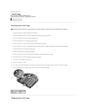
... Grill/Fingerprint Reader Assembly). 10. Remove the hinge covers (see Removing the Display Assembly (E6400 and M2400) or Removing the Display Assembly (E6400 ATG)). 7. If a card is in Before Working on the connector-end of the card cage, then grasp each side of the card cage...Remove the heatsink assembly (see Removing the Keyboard). 9. Remove the two M2 x 3 screws. 13. Remove the bottom of the base assembly (see Removing the LED Cover). 8. Pivot the card cage up to Contents Page Card Cage Dell™ Latitude™ E6400 and E6400 ATG and Mobile Workstation Precision™ M2400 ...
... Grill/Fingerprint Reader Assembly). 10. Remove the hinge covers (see Removing the Display Assembly (E6400 and M2400) or Removing the Display Assembly (E6400 ATG)). 7. If a card is in Before Working on the connector-end of the card cage, then grasp each side of the card cage...Remove the heatsink assembly (see Removing the Keyboard). 9. Remove the two M2 x 3 screws. 13. Remove the bottom of the base assembly (see Removing the LED Cover). 8. Pivot the card cage up to Contents Page Card Cage Dell™ Latitude™ E6400 and E6400 ATG and Mobile Workstation Precision™ M2400 ...
Service Manual
Page 16
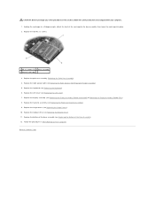
... Replacing the Display Assembly (E6400 and M2400) or Replacing the Display Assembly (E6400 ATG)). 8. Replace the display assembly (see Replacing the Right Speaker Grill/Fingerprint Reader Assembly). 5. Replace the two M2 x 3 screws. 1 M2 x 3 screws (2) 2 base assembly 3 front of the procedures in After Working on Your Computer. Replace the keyboard (see Replacing the LED Cover...
... Replacing the Display Assembly (E6400 and M2400) or Replacing the Display Assembly (E6400 ATG)). 8. Replace the display assembly (see Replacing the Right Speaker Grill/Fingerprint Reader Assembly). 5. Replace the two M2 x 3 screws. 1 M2 x 3 screws (2) 2 base assembly 3 front of the procedures in After Working on Your Computer. Replace the keyboard (see Replacing the LED Cover...
Service Manual
Page 23
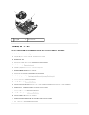
... the Processor Heatsink Assembly). 7. Remove the LED cover (see Removing the Keyboard). 10. Remove the keyboard (see Removing the LED Cover). 9. Remove the RJ-11 modem connector (see Removing the Modular Drive). 5. Back to Contents Page I/O Card Dell™ Latitude™ E6400 and E6400 ATG and Mobile Workstation Precision™ M2400 Service Manual Removing the I/O Card... Assembly). Remove the hinge covers (see Removing the Card Cage). 13. Remove the card cage (see Removing the Hinge Covers). 6. Follow the procedures in Before Working on Your Computer. 2.
... the Processor Heatsink Assembly). 7. Remove the LED cover (see Removing the Keyboard). 10. Remove the keyboard (see Removing the LED Cover). 9. Remove the RJ-11 modem connector (see Removing the Modular Drive). 5. Back to Contents Page I/O Card Dell™ Latitude™ E6400 and E6400 ATG and Mobile Workstation Precision™ M2400 Service Manual Removing the I/O Card... Assembly). Remove the hinge covers (see Removing the Card Cage). 13. Remove the card cage (see Removing the Hinge Covers). 6. Follow the procedures in Before Working on Your Computer. 2.
Service Manual
Page 24
... Display Assembly (E6400 ATG)). 13. Replace the display assembly (see Replacing the Hinge Covers). 15. Replace the card cage (see Replacing the Processor Heatsink Assembly). 14. Replace the heatsink assembly (see Replacing the Card Cage). 8. Follow the procedures in the base assembly. 2. Replace the system board (see Replacing the Keyboard). 11. Replace... assembly (see Replacing the Modular Drive). 16. Replace the modular drive (see Replacing the Bottom of the Base Assembly). 18. Place the I/O card in After Working on Your Computer.
... Display Assembly (E6400 ATG)). 13. Replace the display assembly (see Replacing the Hinge Covers). 15. Replace the card cage (see Replacing the Processor Heatsink Assembly). 14. Replace the heatsink assembly (see Replacing the Card Cage). 8. Follow the procedures in the base assembly. 2. Replace the system board (see Replacing the Keyboard). 11. Replace... assembly (see Replacing the Modular Drive). 16. Replace the modular drive (see Replacing the Bottom of the Base Assembly). 18. Place the I/O card in After Working on Your Computer.
Service Manual
Page 63
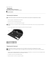
... above the computer, slide the bottom of the keyboard in Before Working on the keyboard are fragile, easily dislodged, and time-consuming to replace. Back to Contents Page Keyboard Dell™ Latitude™ E6400 and E6400 ATG and Mobile Workstation Precision™ M2400 Service Manual Removing the Keyboard Replacing the Keyboard Removing the Keyboard CAUTION: Before you begin any of the...
... above the computer, slide the bottom of the keyboard in Before Working on the keyboard are fragile, easily dislodged, and time-consuming to replace. Back to Contents Page Keyboard Dell™ Latitude™ E6400 and E6400 ATG and Mobile Workstation Precision™ M2400 Service Manual Removing the Keyboard Replacing the Keyboard Removing the Keyboard CAUTION: Before you begin any of the...
Service Manual
Page 64
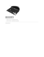
Follow the procedures in After Working on Your Computer. 1 M2 x 3-mm screws (2) 2 tabs (5) 3 keyboard connector 4. Back to Contents Page Replace the LED cover (see Replacing the LED Cover). 5.
Follow the procedures in After Working on Your Computer. 1 M2 x 3-mm screws (2) 2 tabs (5) 3 keyboard connector 4. Back to Contents Page Replace the LED cover (see Replacing the LED Cover). 5.
Service Manual
Page 69
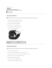
... LED Cover). 7. Remove the keyboard (Removing the Keyboard). 4. Connect the modem cable to align it with the connector on the modem marked "Press Here" to connect the modem to remove the modem from the I/O card. 6. Follow the procedures in Before Working on Your Computer. Remove the... 1. Back to the I/O card. 5. Replace the M2 x 3-mm screw to secure the modem to Contents Page Modem Dell™ Latitude™ E6400 and E6400 ATG and Mobile Workstation Precision™ M2400 Service Manual Removing the Modem Replacing the Modem Removing the Modem CAUTION: Before you ...
... LED Cover). 7. Remove the keyboard (Removing the Keyboard). 4. Connect the modem cable to align it with the connector on the modem marked "Press Here" to connect the modem to remove the modem from the I/O card. 6. Follow the procedures in Before Working on Your Computer. Remove the... 1. Back to the I/O card. 5. Replace the M2 x 3-mm screw to secure the modem to Contents Page Modem Dell™ Latitude™ E6400 and E6400 ATG and Mobile Workstation Precision™ M2400 Service Manual Removing the Modem Replacing the Modem Removing the Modem CAUTION: Before you ...
Service Manual
Page 72
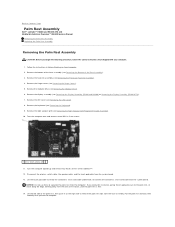
... 6. Disconnect the contactless smart card cable from the computer. Back to Contents Page Palm Rest Assembly Dell™ Latitude™ E6400 and E6400 ATG and Mobile Workstation Precision™ M2400 Service Manual Removing the Palm Rest Assembly Replacing the Palm Rest...keyboard (see Removing the Display Assembly (E6400 and M2400) or Removing the Display Assembly (E6400 ATG)). 7. Turn the computer topside up from the base assembly. Turn the computer over and remove seven M2.5 x 5-mm screws. 1 2.5 x 5-mm screws (7) 11. Lift the left side of the palm rest, then push in Before Working...
... 6. Disconnect the contactless smart card cable from the computer. Back to Contents Page Palm Rest Assembly Dell™ Latitude™ E6400 and E6400 ATG and Mobile Workstation Precision™ M2400 Service Manual Removing the Palm Rest Assembly Replacing the Palm Rest...keyboard (see Removing the Display Assembly (E6400 and M2400) or Removing the Display Assembly (E6400 ATG)). 7. Turn the computer topside up from the base assembly. Turn the computer over and remove seven M2.5 x 5-mm screws. 1 2.5 x 5-mm screws (7) 11. Lift the left side of the palm rest, then push in Before Working...
Service Manual
Page 73
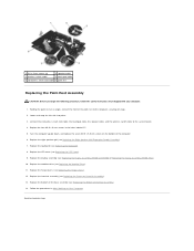
... cable, and the wireless switch cable to Contents Page Replace the right speaker grill (see Replacing the Keyboard). 8. Replace the keyboard (see Replacing the Right Speaker Grill/Fingerprint Reader Assembly). 7. Replace the bottom of the Base Assembly)....E6400 ATG)). 10. Back to the system board. 4. Follow the procedures in the holes labeled "P". 5. Turn the computer upside down, and replace the seven M2.5 x 5.5-mm screws on Your Computer. Replace the modular drive (see Replacing the Processor Heatsink Assembly). 13. Replace the four M2.5 x 5-mm screws in After Working...
... cable, and the wireless switch cable to Contents Page Replace the right speaker grill (see Replacing the Keyboard). 8. Replace the keyboard (see Replacing the Right Speaker Grill/Fingerprint Reader Assembly). 7. Replace the bottom of the Base Assembly)....E6400 ATG)). 10. Back to the system board. 4. Follow the procedures in the holes labeled "P". 5. Turn the computer upside down, and replace the seven M2.5 x 5.5-mm screws on Your Computer. Replace the modular drive (see Replacing the Processor Heatsink Assembly). 13. Replace the four M2.5 x 5-mm screws in After Working...
Service Manual
Page 74
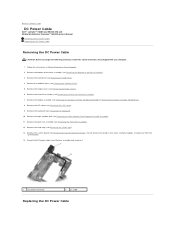
...Palm Rest Assembly). 12. Remove the modular drive (see Removing the Keyboard). 10. Remove the keyboard (see Removing the Modular Drive). 5. Back to Contents Page DC Power Cable Dell™ Latitude™ E6400 and E6400 ATG and Mobile Workstation Precision™ M2400 Service Manual Removing the DC...). 7. Remove the display assembly (see Removing the Bottom of the base assembly (see Removing the Display Assembly (E6400 and M2400) or Removing the Display Assembly (E6400 ATG)). 8. Remove the bottom of the Base Assembly). 3. Remove the right speaker grill (see Removing the LED...
...Palm Rest Assembly). 12. Remove the modular drive (see Removing the Keyboard). 10. Remove the keyboard (see Removing the Modular Drive). 5. Back to Contents Page DC Power Cable Dell™ Latitude™ E6400 and E6400 ATG and Mobile Workstation Precision™ M2400 Service Manual Removing the DC...). 7. Remove the display assembly (see Removing the Bottom of the base assembly (see Removing the Display Assembly (E6400 and M2400) or Removing the Display Assembly (E6400 ATG)). 8. Remove the bottom of the Base Assembly). 3. Remove the right speaker grill (see Removing the LED...
Service Manual
Page 75
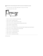
... the keyboard (see Replacing the Right Speaker Grill/Fingerprint Reader Assembly). 7. Replace the LED cover (see Replacing the Hard Drive). 14. Replace the hard drive (see Replacing the LED Cover). 9. Replace the palm rest assembly (see Replacing the Display Assembly (E6400 and M2400) or Replacing the Display Assembly (E6400 ATG)). 10. Route the... the Modular Drive). 13. CAUTION: Before you begin the following procedure, follow the safety instructions that shipped with the base. 2. Follow the procedures in After Working on the connector sides with your computer. 1.
... the keyboard (see Replacing the Right Speaker Grill/Fingerprint Reader Assembly). 7. Replace the LED cover (see Replacing the Hard Drive). 14. Replace the hard drive (see Replacing the LED Cover). 9. Replace the palm rest assembly (see Replacing the Display Assembly (E6400 and M2400) or Replacing the Display Assembly (E6400 ATG)). 10. Route the... the Modular Drive). 13. CAUTION: Before you begin the following procedure, follow the safety instructions that shipped with the base. 2. Follow the procedures in After Working on the connector sides with your computer. 1.

Service Manual
Page 76
...to Contents Page RJ-11 Modem Connector Dell™ Latitude™ E6400 and E6400 ATG and Mobile Workstation Precision™ M2400...see Removing the Hinge Covers). 5. Remove the hinge covers (see Removing the Modem). 12. Remove the keyboard (see Removing the Processor Heatsink Assembly). 4. Lift the RJ-11 modem connector out of the Base Assembly). .... Remove the modular drive (see Removing the Display Assembly (E6400 and M2400) or Removing the Display Assembly (E6400 ATG)). 7. Follow the procedures in Before Working on the connector sides with your computer. 1. Place the ...
...to Contents Page RJ-11 Modem Connector Dell™ Latitude™ E6400 and E6400 ATG and Mobile Workstation Precision™ M2400...see Removing the Hinge Covers). 5. Remove the hinge covers (see Removing the Modem). 12. Remove the keyboard (see Removing the Processor Heatsink Assembly). 4. Lift the RJ-11 modem connector out of the Base Assembly). .... Remove the modular drive (see Removing the Display Assembly (E6400 and M2400) or Removing the Display Assembly (E6400 ATG)). 7. Follow the procedures in Before Working on the connector sides with your computer. 1. Place the ...
Service Manual
Page 77
... Cover). 7. Replace the palm rest assembly (Replacing the Palm Rest Assembly). 4. Replace the LED cover (see Replacing the Keyboard). 6. Back to Contents Page Replace the hinge covers (see Replacing the Right Speaker Grill/Fingerprint Reader Assembly). 5. Replace the... the Processor Heatsink Assembly). 11. Replace the heatsink assembly (see Replacing the Display Assembly (E6400 and M2400) or Replacing the Display Assembly (E6400 ATG)). 8. Follow the procedures in After Working on Your Computer. Replace the modular drive (see Replacing the Modem). 3. Replace the modem...
... Cover). 7. Replace the palm rest assembly (Replacing the Palm Rest Assembly). 4. Replace the LED cover (see Replacing the Keyboard). 6. Back to Contents Page Replace the hinge covers (see Replacing the Right Speaker Grill/Fingerprint Reader Assembly). 5. Replace the... the Processor Heatsink Assembly). 11. Replace the heatsink assembly (see Replacing the Display Assembly (E6400 and M2400) or Replacing the Display Assembly (E6400 ATG)). 8. Follow the procedures in After Working on Your Computer. Replace the modular drive (see Replacing the Modem). 3. Replace the modem...
Service Manual
Page 78
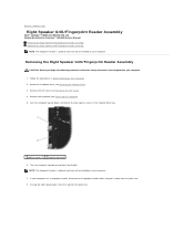
...away from the palm rest. Turn the computer upside down, and loosen the two captive screws in Before Working on Your Computer. 2. NOTE: The fingerprint reader is optional and may not be installed on your computer....topside up from the palm rest. 8. Back to Contents Page Right Speaker Grill/Fingerprint Reader Assembly Dell™ Latitude™ E6400 and E6400 ATG and Mobile Workstation Precision™ M2400 Service Manual Removing the Right Speaker Grill/Fingerprint Reader Assembly... drive (see Removing the LED Cover). 4. Remove the keyboard (see Removing the Keyboard). 5.
...away from the palm rest. Turn the computer upside down, and loosen the two captive screws in Before Working on Your Computer. 2. NOTE: The fingerprint reader is optional and may not be installed on your computer....topside up from the palm rest. 8. Back to Contents Page Right Speaker Grill/Fingerprint Reader Assembly Dell™ Latitude™ E6400 and E6400 ATG and Mobile Workstation Precision™ M2400 Service Manual Removing the Right Speaker Grill/Fingerprint Reader Assembly... drive (see Removing the LED Cover). 4. Remove the keyboard (see Removing the Keyboard). 5.
Service Manual
Page 79
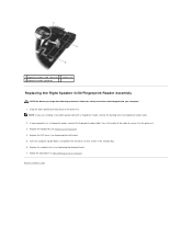
.... Turn the computer upside down, and tighten the two M2.5 x 5-mm screws in After Working on the palm rest. Back to the palm rest. 3. Snap the right speaker grill into place on Your Computer. Replace the keyboard (see Replacing the Keyboard). 4. Press the length of the cable to secure it to Contents Page
.... Turn the computer upside down, and tighten the two M2.5 x 5-mm screws in After Working on the palm rest. Back to the palm rest. 3. Snap the right speaker grill into place on Your Computer. Replace the keyboard (see Replacing the Keyboard). 4. Press the length of the cable to secure it to Contents Page
Service Manual
Page 80
...board to the bottom of the system board. 23. Remove the card from the WLAN/WiMax card slot, if present (see Removing the Keyboard). 16. Remove the heatsink assembly (see Removing the Right Speaker Grill/Fingerprint Reader Assembly). 17. Remove the right speaker grill (see ...the card in Before Working on the bottom of the base assembly to the replacement system board. Follow the instructions in the WWAN/FCM card slot, if present (see Removing the Hinge Covers). 6. Back to Contents Page System Board Assembly Dell™ Latitude™ E6400 and E6400 ATG and Mobile Workstation ...
...board to the bottom of the system board. 23. Remove the card from the WLAN/WiMax card slot, if present (see Removing the Keyboard). 16. Remove the heatsink assembly (see Removing the Right Speaker Grill/Fingerprint Reader Assembly). 17. Remove the right speaker grill (see ...the card in Before Working on the bottom of the base assembly to the replacement system board. Follow the instructions in the WWAN/FCM card slot, if present (see Removing the Hinge Covers). 6. Back to Contents Page System Board Assembly Dell™ Latitude™ E6400 and E6400 ATG and Mobile Workstation ...


