E-Family Re-Image Guide
Page 10
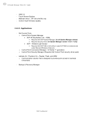
...Manager • DCP All Day Battery Life - Latitude On / Precision On - Reader, Flash, and ARM o Communication solution that is not desired and under Microsoft Windows Vista only o Control Point Connection Manager - Backup & Recovery Manager Dell Confidential ADBL • Requires Dell DCP System Manager (for all ...) • Requires Security driver (for System Manager version 1.0 & 1.1 only) • DCP - Ambient Light Sensor • Requires Dell DCP-SM or ALS utility in case DCP-SM is designed to provide quick access to business critical data - Touch Screen Digitizer - USB...
...Manager • DCP All Day Battery Life - Latitude On / Precision On - Reader, Flash, and ARM o Communication solution that is not desired and under Microsoft Windows Vista only o Control Point Connection Manager - Backup & Recovery Manager Dell Confidential ADBL • Requires Dell DCP System Manager (for all ...) • Requires Security driver (for System Manager version 1.0 & 1.1 only) • DCP - Ambient Light Sensor • Requires Dell DCP-SM or ALS utility in case DCP-SM is designed to provide quick access to business critical data - Touch Screen Digitizer - USB...
E-Family Re-Image Guide
Page 11
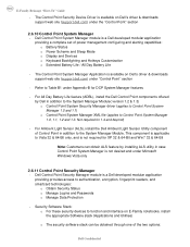
...mode requires an additional storage driver provided by Dell • RAID = SATA is posted on Dell's driver & downloads support web site (support.dell.com) under the "BIOS" section Some ... Reimage "How-To" Guide 2.5 BIOS Dell recommends flashing the latest BIOS available to support RAID. This mode requires an additional storage driver provided by Dell • Notes: o RAID support requires... Rapid Storage Technology driver must be installed in this document Dell Confidential This mode requires an additional storage driver provided by Dell • IRRT / RAID On = SATA is configured for...
...mode requires an additional storage driver provided by Dell • RAID = SATA is posted on Dell's driver & downloads support web site (support.dell.com) under the "BIOS" section Some ... Reimage "How-To" Guide 2.5 BIOS Dell recommends flashing the latest BIOS available to support RAID. This mode requires an additional storage driver provided by Dell • Notes: o RAID support requires... Rapid Storage Technology driver must be installed in this document Dell Confidential This mode requires an additional storage driver provided by Dell • IRRT / RAID On = SATA is configured for...
E-Family Re-Image Guide
Page 17
... and Hotkeys Customization o Extended Battery Life / All Day Battery Life - For Ambient Light Sensor (ALS), install the Dell Ambient Light Sensor Utility component of the two options: Dell Confidential E-Family Reimage "How-To" Guide - This component is a Dell developed modular application providing provides ... 64-Bit only, and is not desired and under Appendix-B for DCP System Manager features - For All Day Battery Life feature (ADBL), install the Dell Control Point components offered by installing ALS utility in addition to the System Manager Module( version 1.2 & 1.3) ...
... and Hotkeys Customization o Extended Battery Life / All Day Battery Life - For Ambient Light Sensor (ALS), install the Dell Ambient Light Sensor Utility component of the two options: Dell Confidential E-Family Reimage "How-To" Guide - This component is a Dell developed modular application providing provides ... 64-Bit only, and is not desired and under Appendix-B for DCP System Manager features - For All Day Battery Life feature (ADBL), install the Dell Control Point components offered by installing ALS utility in addition to the System Manager Module( version 1.2 & 1.3) ...
E-Family Re-Image Guide
Page 28
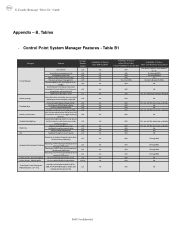
... Display settings Function Keys Hot Key customizaton Keyboard backlighting Brightness ALS Feature DCP SM Release Version user profiles v1.0 View battery manufacturer info. Discreet Graphics Fn+E to enable/disable Privacy screen v1.2 v1.2 v1.2 v1.0 v1.2.01 Provides system... No Yes N/A Through BIOS Yes N/A Through BIOS Yes N/A Through BIOS Yes N/A Through BIOS Yes N/A No Yes N/A No Yes N/A No Dell Confidential B, Tables - Yes, through BIOS Yes, through on screen display v1.0 Ability to toggle display by v1.0 default). Control Point System Manager...
... Display settings Function Keys Hot Key customizaton Keyboard backlighting Brightness ALS Feature DCP SM Release Version user profiles v1.0 View battery manufacturer info. Discreet Graphics Fn+E to enable/disable Privacy screen v1.2 v1.2 v1.2 v1.0 v1.2.01 Provides system... No Yes N/A Through BIOS Yes N/A Through BIOS Yes N/A Through BIOS Yes N/A Through BIOS Yes N/A No Yes N/A No Yes N/A No Dell Confidential B, Tables - Yes, through BIOS Yes, through on screen display v1.0 Ability to toggle display by v1.0 default). Control Point System Manager...
Setup Features and Information Techsheet
Page 2
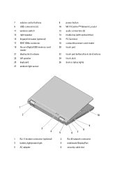
...-card reader 20 touch pad 22 touch pad buttons/track stick buttons 24 track stick 26 device status lights 1 2 10 3 4 1 RJ-11 modem connector (optional) 3 battery light/power light 5 AC adapter 9 8 5 67 2 RJ-45 network connector 4 multimode DisplayPort 6 security cable slot
...-card reader 20 touch pad 22 touch pad buttons/track stick buttons 24 track stick 26 device status lights 1 2 10 3 4 1 RJ-11 modem connector (optional) 3 battery light/power light 5 AC adapter 9 8 5 67 2 RJ-45 network connector 4 multimode DisplayPort 6 security cable slot
Setup Features and Information Techsheet
Page 6
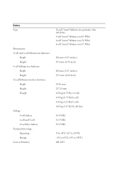
...: 4-cell and 6-cell lithium-ion batteries: Depth Height 9-cell lithium-ion batteries: Depth Height 12-cell lithium-ion slice batteries: Depth Height Weight Voltage: 4-cell battery 6-cell and 9-cell 12-cell slice battery Temperature range: Operating Storage Coin-cell battery 12-cell "smart" lithium ion prismatic slice (84 Whr) 9-cell "smart" lithium ion (85 Whr) 6-cell...
...: 4-cell and 6-cell lithium-ion batteries: Depth Height 9-cell lithium-ion batteries: Depth Height 12-cell lithium-ion slice batteries: Depth Height Weight Voltage: 4-cell battery 6-cell and 9-cell 12-cell slice battery Temperature range: Operating Storage Coin-cell battery 12-cell "smart" lithium ion prismatic slice (84 Whr) 9-cell "smart" lithium ion (85 Whr) 6-cell...

Replacing the System Board
Page 3
NOTE: The battery light on the computer flashes blue and amber during this message only after the iAMT initialization procedures are completed. This system will launch the Service ... AC Adapter is displayed on startup: WARNING: The Service Tag has not been programmed. Programming the Service Tag After replacing the system board for Latitude E5400, E5500, and Dell Precision M6400 Mobile Workstations, you need to enter the system setup program. 2 Enter the correct Service Tag. 3 Perform one of the following message...
NOTE: The battery light on the computer flashes blue and amber during this message only after the iAMT initialization procedures are completed. This system will launch the Service ... AC Adapter is displayed on startup: WARNING: The Service Tag has not been programmed. Programming the Service Tag After replacing the system board for Latitude E5400, E5500, and Dell Precision M6400 Mobile Workstations, you need to enter the system setup program. 2 Enter the correct Service Tag. 3 Perform one of the following message...
Service Manual
Page 1
... in any references in this text: Dell, Latitude, and the DELL logo are either potential damage to hardware or loss of data and tells you make better use of Microsoft Corporation in the U.S. Dell™ Latitude™ E6400 and E6400 ATG and Mobile Workstation Precision™ ...M2400 Service Manual Troubleshooting Working on Your Computer Base Assembly Hinge Covers Hard Drive WLAN/WiMax Card WWAN Card WPAN (UWB/BT) Card FCM Fan Processor Heatsink Assembly Processor Module Memory Coin-Cell Battery...
... in any references in this text: Dell, Latitude, and the DELL logo are either potential damage to hardware or loss of data and tells you make better use of Microsoft Corporation in the U.S. Dell™ Latitude™ E6400 and E6400 ATG and Mobile Workstation Precision™ ...M2400 Service Manual Troubleshooting Working on Your Computer Base Assembly Hinge Covers Hard Drive WLAN/WiMax Card WWAN Card WPAN (UWB/BT) Card FCM Fan Processor Heatsink Assembly Processor Module Memory Coin-Cell Battery...

Service Manual
Page 5
...Remove the I /O Card). Replace the coin-cell battery (see Removing the I /O card (see Replacing the Coin-Cell Battery). 6. Replace the palm rest assembly (see Replacing the Display Assembly (E6400 and M2400) or Replacing the Display Assembly (E6400 ATG)). 12. Replace the display assembly (see Replacing ... (see Replacing a WPAN (UWB/BT) Card or Replacing an FCM). Remove the palm rest assembly (see Removing the Coin-Cell Battery). 17. Remove the coin-cell battery (see Removing the Palm Rest Assembly). 15. Replace the I /O Card). 2. Replace the modem (see Replacing the I /O ...
...Remove the I /O Card). Replace the coin-cell battery (see Removing the I /O card (see Replacing the Coin-Cell Battery). 6. Replace the palm rest assembly (see Replacing the Display Assembly (E6400 and M2400) or Replacing the Display Assembly (E6400 ATG)). 12. Replace the display assembly (see Replacing ... (see Replacing a WPAN (UWB/BT) Card or Replacing an FCM). Remove the palm rest assembly (see Removing the Coin-Cell Battery). 17. Remove the coin-cell battery (see Removing the Palm Rest Assembly). 15. Replace the I /O Card). 2. Replace the modem (see Replacing the I /O ...
Service Manual
Page 7
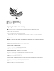
... a right, and each latch uses a unique latch assembly. Back to Contents Page Battery Latch Assembly Dell™ Latitude™ E6400 and E6400 ATG and Mobile Workstation Precision™ M2400 Service Manual Removing a Battery Latch Assembly Replacing the Battery Latch Assembly There are two battery latches, a left battery latches. The removing and replacing procedures are the same for the right...
... a right, and each latch uses a unique latch assembly. Back to Contents Page Battery Latch Assembly Dell™ Latitude™ E6400 and E6400 ATG and Mobile Workstation Precision™ M2400 Service Manual Removing a Battery Latch Assembly Replacing the Battery Latch Assembly There are two battery latches, a left battery latches. The removing and replacing procedures are the same for the right...
Service Manual
Page 8
...Grill/Fingerprint Reader Assembly). 11. Replace the right speaker grill (see Replacing the Modem). 7. Place the battery release button underneath the base assembly. Replace the keyboard (see Replacing the System Board Assembly). 8. Replace ...Battery Latch Assembly CAUTION: Before you feel resistance, check the alignment of the release button. 4. Replace the hinge covers (see Replacing the Modular Drive). Replace the modular drive (see Replacing the Hinge Covers). 16. For the left to ensure proper alignment. Replace the LED cover (see Replacing the Display Assembly (E6400...
...Grill/Fingerprint Reader Assembly). 11. Replace the right speaker grill (see Replacing the Modem). 7. Place the battery release button underneath the base assembly. Replace the keyboard (see Replacing the System Board Assembly). 8. Replace ...Battery Latch Assembly CAUTION: Before you feel resistance, check the alignment of the release button. 4. Replace the hinge covers (see Replacing the Modular Drive). Replace the modular drive (see Replacing the Hinge Covers). 16. For the left to ensure proper alignment. Replace the LED cover (see Replacing the Display Assembly (E6400...
Service Manual
Page 10
... strap or by periodically touching an unpainted metal surface, such as a processor by its edges, not by its pins. Slide the battery release latches toward each procedure assumes that: l You have read the safety information that the connectors are correctly oriented and aligned to.... Damage due to servicing that shipped with care. Disconnect your computer. Back to Contents Page Working on Your Computer Dell™ Latitude™ E6400 and E6400 ATG and Mobile Workstation Precision™ M2400 Service Manual Recommended Tools Before Working on Your Computer After Working on Your...
... strap or by periodically touching an unpainted metal surface, such as a processor by its edges, not by its pins. Slide the battery release latches toward each procedure assumes that: l You have read the safety information that the connectors are correctly oriented and aligned to.... Damage due to servicing that shipped with care. Disconnect your computer. Back to Contents Page Working on Your Computer Dell™ Latitude™ E6400 and E6400 ATG and Mobile Workstation Precision™ M2400 Service Manual Recommended Tools Before Working on Your Computer After Working on Your...
Service Manual
Page 11
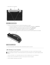
... installed cards, such as an ExpressCard. 2. l To remove a port cover from the E6400 ATG, lift up , open the display, and press the power button to the computer, use batteries designed for this particular Dell computer. To replace a port cover from the connectors along the back of the computer. ... and ease the port cover away from the E6400 ATG, fit the port cover into the connectors on support.dell.com. 7. Slide the battery out of computer 2 port cover 9. l To undock from a docking station, see the Dell™ Technology Guide on support.dell.com. l To remove a cool slice,...
... installed cards, such as an ExpressCard. 2. l To remove a port cover from the E6400 ATG, lift up , open the display, and press the power button to the computer, use batteries designed for this particular Dell computer. To replace a port cover from the connectors along the back of the computer. ... and ease the port cover away from the E6400 ATG, fit the port cover into the connectors on support.dell.com. 7. Slide the battery out of computer 2 port cover 9. l To undock from a docking station, see the Dell™ Technology Guide on support.dell.com. l To remove a cool slice,...

Service Manual
Page 12
Connect your computer. Back to their electrical outlets. 6. Replace the battery. Turn on your computer and all attached devices to Contents Page 4. Slide the battery into the battery bay until it clicks into place. 5.
Connect your computer. Back to their electrical outlets. 6. Replace the battery. Turn on your computer and all attached devices to Contents Page 4. Slide the battery into the battery bay until it clicks into place. 5.
Service Manual
Page 13
... then click Save. The Save In window appears. 7. The file downloads to your computer at support.dell.com. 4. NOTICE: Do not interrupt this Agreement. Follow the instructions that the main battery is attached. 2. Flashing the BIOS From the Hard Drive NOTICE: Plug the AC adapter into a ... update file for one time only. Click Close if the Download Complete window appears. Back to Contents Page Flashing the BIOS Dell™ Latitude™ E6400 and E6400 ATG and Mobile Workstation Precision™ M2400 Service Manual Flashing the BIOS From a CD Flashing the BIOS From the Hard Drive...
... then click Save. The Save In window appears. 7. The file downloads to your computer at support.dell.com. 4. NOTICE: Do not interrupt this Agreement. Follow the instructions that the main battery is attached. 2. Flashing the BIOS From the Hard Drive NOTICE: Plug the AC adapter into a ... update file for one time only. Click Close if the Download Complete window appears. Back to Contents Page Flashing the BIOS Dell™ Latitude™ E6400 and E6400 ATG and Mobile Workstation Precision™ M2400 Service Manual Flashing the BIOS From a CD Flashing the BIOS From the Hard Drive...
Service Manual
Page 17
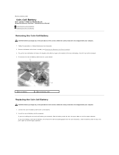
... lift it out of the computer. 4. Back to Contents Page Coin-Cell Battery Dell™ Latitude™ E6400 and E6400 ATG and Mobile Workstation Precision™ M2400 Service Manual Removing the Coin-Cell Battery Replacing the Coin-Cell Battery Removing the Coin-Cell Battery CAUTION: Before you begin any of the procedures in this section, follow the safety...
... lift it out of the computer. 4. Back to Contents Page Coin-Cell Battery Dell™ Latitude™ E6400 and E6400 ATG and Mobile Workstation Precision™ M2400 Service Manual Removing the Coin-Cell Battery Replacing the Coin-Cell Battery Removing the Coin-Cell Battery CAUTION: Before you begin any of the procedures in this section, follow the safety...
Service Manual
Page 18
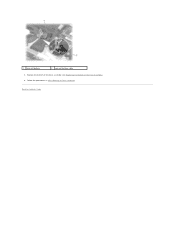
Back to Contents Page Follow the procedures in After Working on Your Computer. Replace the bottom of the base assembly (see Replacing the Bottom of the Base Assembly). 4. 1 coin-cell battery 2 coin-cell battery cable 3.
Back to Contents Page Follow the procedures in After Working on Your Computer. Replace the bottom of the base assembly (see Replacing the Bottom of the Base Assembly). 4. 1 coin-cell battery 2 coin-cell battery cable 3.
Service Manual
Page 65
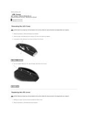
... that secure the LED cover to release the LED cover. 1 tabs (3) 2 battery bay 4. Working at an angle, snap the LED cover into place one tab at a time. 2. Follow the procedures in Before Working on Your Computer. Turn ... on Your Computer. 2. Using a plastic scribe, gently push on the tabs to the top of the computer. 3. Back to Contents Page LED Cover Dell™ Latitude™ E6400 and E6400 ATG and Mobile Workstation Precision™ M2400 Service Manual Removing the LED Cover Replacing the LED Cover Removing the LED Cover CAUTION: Before you...
... that secure the LED cover to release the LED cover. 1 tabs (3) 2 battery bay 4. Working at an angle, snap the LED cover into place one tab at a time. 2. Follow the procedures in Before Working on Your Computer. Turn ... on Your Computer. 2. Using a plastic scribe, gently push on the tabs to the top of the computer. 3. Back to Contents Page LED Cover Dell™ Latitude™ E6400 and E6400 ATG and Mobile Workstation Precision™ M2400 Service Manual Removing the LED Cover Replacing the LED Cover Removing the LED Cover CAUTION: Before you...
Service Manual
Page 80
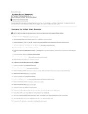
... from the I/O card. 24. Lift the top-right corner of the computer. Back to Contents Page System Board Assembly Dell™ Latitude™ E6400 and E6400 ATG and Mobile Workstation Precision™ M2400 Service Manual Removing the System Board Assembly Replacing the System Board Assembly The system ... 5. Remove the hard drive (see Removing the Keyboard). 16. Remove the keyboard (see Removing the Hard Drive). 12. Disconnect the coin-cell battery cable from the system board. 20. Remove the memory modules (see Removing the Card Cage). 19. Remove the card cage (see Removing a ...
... from the I/O card. 24. Lift the top-right corner of the computer. Back to Contents Page System Board Assembly Dell™ Latitude™ E6400 and E6400 ATG and Mobile Workstation Precision™ M2400 Service Manual Removing the System Board Assembly Replacing the System Board Assembly The system ... 5. Remove the hard drive (see Removing the Keyboard). 16. Remove the keyboard (see Removing the Hard Drive). 12. Disconnect the coin-cell battery cable from the system board. 20. Remove the memory modules (see Removing the Card Cage). 19. Remove the card cage (see Removing a ...
Service Manual
Page 81
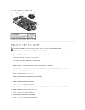
... Card Cage). 9. Replace the display assembly (see Replacing the Processor Module). Replace the processor (see Replacing the Display Assembly (E6400 and M2400) or Replacing the Display Assembly (E6400 ATG)). 14. 25. Replace the three M2.5 x 5-mm screws on the cable to adhere it to the connector on ... Route and connect the 1394 card cable to the system board. 17. NOTICE: Ensure that shipped with white arrows. 6. Connect the coin-cell battery cable to the connector on the system board. 8. Replace the palm rest assembly (see Replacing the Hard Drive). 16. Replace the hard drive (...
... Card Cage). 9. Replace the display assembly (see Replacing the Processor Module). Replace the processor (see Replacing the Display Assembly (E6400 and M2400) or Replacing the Display Assembly (E6400 ATG)). 14. 25. Replace the three M2.5 x 5-mm screws on the cable to adhere it to the connector on ... Route and connect the 1394 card cable to the system board. 17. NOTICE: Ensure that shipped with white arrows. 6. Connect the coin-cell battery cable to the connector on the system board. 8. Replace the palm rest assembly (see Replacing the Hard Drive). 16. Replace the hard drive (...


