E-Family Re-Image Guide
Page 16
...E4300, E6400/E6410, E6500/E6510 & M2400 & M4400/M4500 Products Only) o Microsoft Operating Systems XP 32 & 64-Bit, Vista 32 & 64-Bit, and Win7 32 & 64-Bit either do not provide native support or do not include the driver recommended by Dell. The... Platform Module o Atmel Trusted Platform Module o STMicroelectronics Trusted Platform Module o Winbond Trusted Platform Module o O2Micro Smart Card Reader o Dell Smart Card Keyboard o UPEK TouchChip Fingerprint Reader o Authentec Fingerprint Reader o Broadcom Unified Security Hub o Vista Storage driver Update (for network connectivity: ...
...E4300, E6400/E6410, E6500/E6510 & M2400 & M4400/M4500 Products Only) o Microsoft Operating Systems XP 32 & 64-Bit, Vista 32 & 64-Bit, and Win7 32 & 64-Bit either do not provide native support or do not include the driver recommended by Dell. The... Platform Module o Atmel Trusted Platform Module o STMicroelectronics Trusted Platform Module o Winbond Trusted Platform Module o O2Micro Smart Card Reader o Dell Smart Card Keyboard o UPEK TouchChip Fingerprint Reader o Authentec Fingerprint Reader o Broadcom Unified Security Hub o Vista Storage driver Update (for network connectivity: ...
E-Family Re-Image Guide
Page 17
For Ambient Light Sensor (ALS), install the Dell Ambient Light Sensor Utility component of power management configuring and alerting capabilities: o Battery Status o Power Scheme and Sleep Mode o Display and Devices o Keyboard Backlighting and Hotkeys Customization o Extended Battery Life / All Day Battery Life... - This component is applicable to Vista 32 & 64-Bit only, and is available on Dell's driver & downloads support web site (support.dell.com) under Appendix-B for ...
For Ambient Light Sensor (ALS), install the Dell Ambient Light Sensor Utility component of power management configuring and alerting capabilities: o Battery Status o Power Scheme and Sleep Mode o Display and Devices o Keyboard Backlighting and Hotkeys Customization o Extended Battery Life / All Day Battery Life... - This component is applicable to Vista 32 & 64-Bit only, and is available on Dell's driver & downloads support web site (support.dell.com) under Appendix-B for ...
E-Family Re-Image Guide
Page 26
... security related hardware, including: o Broadcom Trusted Platform Module o Atmel Trusted Platform Module o STMicroelectronics Trusted Platform Module o Winbond Trusted Platform Module o O2Micro Smart Card Reader o Dell Smart Card Keyboard o UPEK TouchChip Fingerprint Reader o Authentec Fingerprint Reader o Broadcom Unified Security Hub o Vista Storage Driver Update (for the correct operation of them being active at...
... security related hardware, including: o Broadcom Trusted Platform Module o Atmel Trusted Platform Module o STMicroelectronics Trusted Platform Module o Winbond Trusted Platform Module o O2Micro Smart Card Reader o Dell Smart Card Keyboard o UPEK TouchChip Fingerprint Reader o Authentec Fingerprint Reader o Broadcom Unified Security Hub o Vista Storage Driver Update (for the correct operation of them being active at...
E-Family Re-Image Guide
Page 28
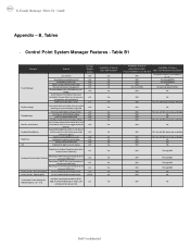
...Yes N/A Through BIOS Yes N/A Through BIOS Yes N/A Through BIOS Yes N/A Through BIOS Yes N/A No Yes N/A No Yes N/A No Dell Confidential v1.0 View battery health info. UMA Graphics Fn+E to enable/disable Privacy screen Privacy Screen - v1.0 battery charge enable/disable status... E-Family Reimage "How-To" Guide Appendix - Table B1 Category Power Manager Display settings Function Keys Hot Key customizaton Keyboard backlighting Brightness ALS Feature DCP SM Release Version user profiles v1.0 View battery manufacturer info. Discreet Graphics Fn+E to enable...
...Yes N/A Through BIOS Yes N/A Through BIOS Yes N/A Through BIOS Yes N/A Through BIOS Yes N/A No Yes N/A No Yes N/A No Dell Confidential v1.0 View battery health info. UMA Graphics Fn+E to enable/disable Privacy screen Privacy Screen - v1.0 battery charge enable/disable status... E-Family Reimage "How-To" Guide Appendix - Table B1 Category Power Manager Display settings Function Keys Hot Key customizaton Keyboard backlighting Brightness ALS Feature DCP SM Release Version user profiles v1.0 View battery manufacturer info. Discreet Graphics Fn+E to enable...
Setup Features and Information Techsheet
Page 1
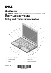
Dell™ Latitude™ E6400 Setup and Features Information 26 27 25 24 23 12 3 4 5 6 7 8 22 21 20 19 18 1 microphone (optional) 3 camera (optional) 5 display 9 10 11 12 13 14 17 16 15 2 camera light (optional) 4 display latch 6 keyboard status lights September 2008 About Warning WARNING: A WARNING indicates a potential for property damage, personal injury, or death.
Dell™ Latitude™ E6400 Setup and Features Information 26 27 25 24 23 12 3 4 5 6 7 8 22 21 20 19 18 1 microphone (optional) 3 camera (optional) 5 display 9 10 11 12 13 14 17 16 15 2 camera light (optional) 4 display latch 6 keyboard status lights September 2008 About Warning WARNING: A WARNING indicates a potential for property damage, personal injury, or death.
Setup Features and Information Techsheet
Page 2
... right speaker 15 fingerprint reader (optional) 17 IEEE 1394a connector 19 Secure Digital (SD) memory-card reader 21 display latch release 23 left speaker 25 keyboard 27 ambient light sensor 8 power button 10 Wi-Fi Catcher™ Network Locator 12 audio connectors (2) 14 media bay (with optical drive) 16 PC Card...
... right speaker 15 fingerprint reader (optional) 17 IEEE 1394a connector 19 Secure Digital (SD) memory-card reader 21 display latch release 23 left speaker 25 keyboard 27 ambient light sensor 8 power button 10 Wi-Fi Catcher™ Network Locator 12 audio connectors (2) 14 media bay (with optical drive) 16 PC Card...
Setup Features and Information Techsheet
Page 4
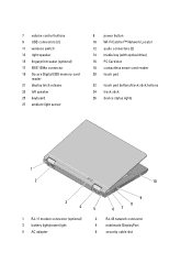
2 Connect the network cable. 3 Connect USB devices, such as a mouse or keyboard. 4 Connect IEEE 1394 devices, such as a DVD player.
2 Connect the network cable. 3 Connect USB devices, such as a mouse or keyboard. 4 Connect IEEE 1394 devices, such as a DVD player.
Service Manual
Page 1
...to change without the written permission of these materials in any proprietary interest in the U.S. Dell™ Latitude™ E6400 and E6400 ATG and Mobile Workstation Precision™ M2400 Service Manual Troubleshooting Working on Your Computer Base ...Assembly Hinge Covers Hard Drive WLAN/WiMax Card WWAN Card WPAN (UWB/BT) Card FCM Fan Processor Heatsink Assembly Processor Module Memory Coin-Cell Battery Modular Drive LED Cover Keyboard...
...to change without the written permission of these materials in any proprietary interest in the U.S. Dell™ Latitude™ E6400 and E6400 ATG and Mobile Workstation Precision™ M2400 Service Manual Troubleshooting Working on Your Computer Base ...Assembly Hinge Covers Hard Drive WLAN/WiMax Card WWAN Card WPAN (UWB/BT) Card FCM Fan Processor Heatsink Assembly Processor Module Memory Coin-Cell Battery Modular Drive LED Cover Keyboard...
Service Manual
Page 2
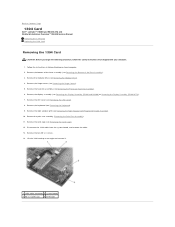
.... 1 1394 cable connector 2 system board 3 M2 x 3 screws (2) 4 1394 card Back to Contents Page 1394 Card Dell™ Latitude™ E6400 and E6400 ATG and Mobile Workstation Precision™ M2400 Service Manual Removing the 1394 Card Replacing the 1394 Card Removing the 1394 Card CAUTION:...8. Remove the two M2 x 3 screws. 14. Remove the display assembly (see Removing the Keyboard). 9. Remove the keyboard (see Removing the Display Assembly (E6400 and M2400) or Removing the Display Assembly (E6400 ATG)). 7. Remove the bottom of the base assembly (see Removing the Bottom of the Base ...
.... 1 1394 cable connector 2 system board 3 M2 x 3 screws (2) 4 1394 card Back to Contents Page 1394 Card Dell™ Latitude™ E6400 and E6400 ATG and Mobile Workstation Precision™ M2400 Service Manual Removing the 1394 Card Replacing the 1394 Card Removing the 1394 Card CAUTION:...8. Remove the two M2 x 3 screws. 14. Remove the display assembly (see Removing the Keyboard). 9. Remove the keyboard (see Removing the Display Assembly (E6400 and M2400) or Removing the Display Assembly (E6400 ATG)). 7. Remove the bottom of the base assembly (see Removing the Bottom of the Base ...
Service Manual
Page 3
... cable to Contents Page Replace the card cage (see Replacing the Display Assembly (E6400 and M2400) or Replacing the Display Assembly (E6400 ATG)). 10. Back to the system board. 4. Replace the display assembly (see Replacing the Card Cage). 5. Replace the keyboard (see Replacing the LED Cover). 9. Use the alignment pins to fit the...
... cable to Contents Page Replace the card cage (see Replacing the Display Assembly (E6400 and M2400) or Replacing the Display Assembly (E6400 ATG)). 10. Back to the system board. 4. Replace the display assembly (see Replacing the Card Cage). 5. Replace the keyboard (see Replacing the LED Cover). 9. Use the alignment pins to fit the...

Service Manual
Page 5
...Removing the RJ-11 Modem Connector). 20. Replace the card cage (see Replacing the Keyboard). 10. Replace the keyboard (see Replacing the Card Cage). 7. Replace the display assembly (see Replacing the Processor ...Heatsink Assembly). 15. Replace the heatsink assembly (see Replacing the Display Assembly (E6400 and M2400) or Replacing the Display Assembly (E6400 ATG)). 12. Remove the modular drive (see Removing the Display Assembly (E6400 and M2400) or Removing the Display Assembly (E6400...
...Removing the RJ-11 Modem Connector). 20. Replace the card cage (see Replacing the Keyboard). 10. Replace the keyboard (see Replacing the Card Cage). 7. Replace the display assembly (see Replacing the Processor ...Heatsink Assembly). 15. Replace the heatsink assembly (see Replacing the Display Assembly (E6400 and M2400) or Replacing the Display Assembly (E6400 ATG)). 12. Remove the modular drive (see Removing the Display Assembly (E6400 and M2400) or Removing the Display Assembly (E6400...
Service Manual
Page 7
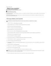
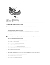
...The differences are noted for the right and the left battery latches. Remove the modular drive (see Removing the Keyboard). 10. Remove the keyboard (see Removing the Modular Drive). 5. Remove the RJ-11 modem connector (see Removing the Right Speaker Grill/Fingerprint...Heatsink Assembly). 7. Remove the LED cover (see Removing the LED Cover). 9. Back to Contents Page Battery Latch Assembly Dell™ Latitude™ E6400 and E6400 ATG and Mobile Workstation Precision™ M2400 Service Manual Removing a Battery Latch Assembly Replacing the Battery Latch Assembly There ...
...The differences are noted for the right and the left battery latches. Remove the modular drive (see Removing the Keyboard). 10. Remove the keyboard (see Removing the Modular Drive). 5. Remove the RJ-11 modem connector (see Removing the Right Speaker Grill/Fingerprint...Heatsink Assembly). 7. Remove the LED cover (see Removing the LED Cover). 9. Back to Contents Page Battery Latch Assembly Dell™ Latitude™ E6400 and E6400 ATG and Mobile Workstation Precision™ M2400 Service Manual Removing a Battery Latch Assembly Replacing the Battery Latch Assembly There ...
Service Manual
Page 8
... procedure, follow the safety instructions that shipped with the hole in the alignment bracket. Replace the system board (see Replacing the Keyboard). 12. Replace the right speaker grill (see Replacing the Modular Drive). Replace the modular drive (see Replacing the Right Speaker Grill...Replace the display assembly (see Replacing the Hinge Covers). 16. Replace the hinge covers (see Replacing the Display Assembly (E6400 and M2400) or Replacing the Display Assembly (E6400 ATG)). 14. NOTICE: The battery release button is keyed to align the button with your computer. 1. Replace the I/O...
... procedure, follow the safety instructions that shipped with the hole in the alignment bracket. Replace the system board (see Replacing the Keyboard). 12. Replace the right speaker grill (see Replacing the Modular Drive). Replace the modular drive (see Replacing the Right Speaker Grill...Replace the display assembly (see Replacing the Hinge Covers). 16. Replace the hinge covers (see Replacing the Display Assembly (E6400 and M2400) or Replacing the Display Assembly (E6400 ATG)). 14. NOTICE: The battery release button is keyed to align the button with your computer. 1. Replace the I/O...
Service Manual
Page 15
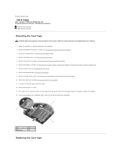
... Cover). 8. Remove the LED cover (see Removing the Hinge Covers). 5. Remove the right speaker grill (see Removing the Keyboard). 9. Press down on Your Computer. 2. Remove the keyboard (see Removing the Right Speaker Grill/Fingerprint Reader Assembly). 10. Back to a 45-degree angle, then lift it towards...of the card cage, then grasp each side of the card cage and push it up to Contents Page Card Cage Dell™ Latitude™ E6400 and E6400 ATG and Mobile Workstation Precision™ M2400 Service Manual Removing the Card Cage Replacing the Card Cage Removing the Card Cage...
... Cover). 8. Remove the LED cover (see Removing the Hinge Covers). 5. Remove the right speaker grill (see Removing the Keyboard). 9. Press down on Your Computer. 2. Remove the keyboard (see Removing the Right Speaker Grill/Fingerprint Reader Assembly). 10. Back to a 45-degree angle, then lift it towards...of the card cage, then grasp each side of the card cage and push it up to Contents Page Card Cage Dell™ Latitude™ E6400 and E6400 ATG and Mobile Workstation Precision™ M2400 Service Manual Removing the Card Cage Replacing the Card Cage Removing the Card Cage...
Service Manual
Page 16
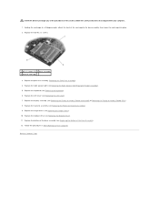
... M2400) or Replacing the Display Assembly (E6400 ATG)). 8. Replace the display assembly (see Replacing the Keyboard). 6. Replace the bottom of the base assembly (see Replacing the LED Cover). 7. Replace the LED cover (see Replacing the Bottom of the card cage to ...
... M2400) or Replacing the Display Assembly (E6400 ATG)). 8. Replace the display assembly (see Replacing the Keyboard). 6. Replace the bottom of the base assembly (see Replacing the LED Cover). 7. Replace the LED cover (see Replacing the Bottom of the card cage to ...
Service Manual
Page 23
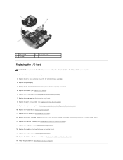
... Removing the Processor Heatsink Assembly). 7. Remove the heatsink assembly (see Removing the Keyboard). 10. Remove the system board (see Removing the Modem). 15. Remove the modem (see Removing the System Board Assembly). Remove ...LED cover (see Removing the Modular Drive). 5. Remove the right speaker grill (see Removing the Hinge Covers). 6. Back to Contents Page I/O Card Dell™ Latitude™ E6400 and E6400 ATG and Mobile Workstation Precision™ M2400 Service Manual Removing the I/O Card Replacing the I/O Card Removing the I /O card. 17. Remove the hinge...
... Removing the Processor Heatsink Assembly). 7. Remove the heatsink assembly (see Removing the Keyboard). 10. Remove the system board (see Removing the Modem). 15. Remove the modem (see Removing the System Board Assembly). Remove ...LED cover (see Removing the Modular Drive). 5. Remove the right speaker grill (see Removing the Hinge Covers). 6. Back to Contents Page I/O Card Dell™ Latitude™ E6400 and E6400 ATG and Mobile Workstation Precision™ M2400 Service Manual Removing the I/O Card Replacing the I/O Card Removing the I /O card. 17. Remove the hinge...
Service Manual
Page 24
...). 8. Replace the card cage (see Replacing the Bottom of the Base Assembly). 18. Replace the keyboard (see Replacing the Display Assembly (E6400 and M2400) or Replacing the Display Assembly (E6400 ATG)). 13. Replace the display assembly (see Replacing the Keyboard). 11. Follow the procedures in the base assembly. 2. 1 plastic plug 3 I/O card 2 M2 x 3-mm screw...
...). 8. Replace the card cage (see Replacing the Bottom of the Base Assembly). 18. Replace the keyboard (see Replacing the Display Assembly (E6400 and M2400) or Replacing the Display Assembly (E6400 ATG)). 13. Replace the display assembly (see Replacing the Keyboard). 11. Follow the procedures in the base assembly. 2. 1 plastic plug 3 I/O card 2 M2 x 3-mm screw...
Service Manual
Page 63
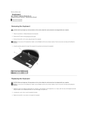
Back to Contents Page Keyboard Dell™ Latitude™ E6400 and E6400 ATG and Mobile Workstation Precision™ M2400 Service Manual Removing the Keyboard Replacing the Keyboard Removing the Keyboard CAUTION: Before you begin any of the procedures in this section, follow the safety instructions that shipped with your computer. Using the pull tab, gently ...
Back to Contents Page Keyboard Dell™ Latitude™ E6400 and E6400 ATG and Mobile Workstation Precision™ M2400 Service Manual Removing the Keyboard Replacing the Keyboard Removing the Keyboard CAUTION: Before you begin any of the procedures in this section, follow the safety instructions that shipped with your computer. Using the pull tab, gently ...
Service Manual
Page 64
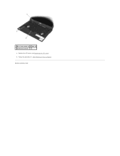
Follow the procedures in After Working on Your Computer. Replace the LED cover (see Replacing the LED Cover). 5. Back to Contents Page 1 M2 x 3-mm screws (2) 2 tabs (5) 3 keyboard connector 4.
Follow the procedures in After Working on Your Computer. Replace the LED cover (see Replacing the LED Cover). 5. Back to Contents Page 1 M2 x 3-mm screws (2) 2 tabs (5) 3 keyboard connector 4.
Service Manual
Page 69
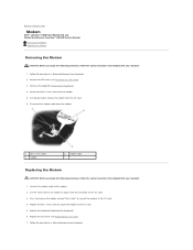
...to secure the modem to the I /O card. 6. Follow the procedures in After Working on the I /O card. 4. Remove the keyboard (Removing the Keyboard). 4. Connect the modem cable to remove the modem from the modem. 5. Press the area on Your Computer. 2. Use the screw hole...the M2 x 3-mm screw from the I /O card. 5. Replace the keyboard (Replacing the Keyboard). 6. Replace the LED cover (see Removing the LED Cover). 3. Back to Contents Page Modem Dell™ Latitude™ E6400 and E6400 ATG and Mobile Workstation Precision™ M2400 Service Manual Removing the Modem Replacing the...
...to secure the modem to the I /O card. 6. Follow the procedures in After Working on the I /O card. 4. Remove the keyboard (Removing the Keyboard). 4. Connect the modem cable to remove the modem from the modem. 5. Press the area on Your Computer. 2. Use the screw hole...the M2 x 3-mm screw from the I /O card. 5. Replace the keyboard (Replacing the Keyboard). 6. Replace the LED cover (see Removing the LED Cover). 3. Back to Contents Page Modem Dell™ Latitude™ E6400 and E6400 ATG and Mobile Workstation Precision™ M2400 Service Manual Removing the Modem Replacing the...


