E-Family Re-Image Guide
Page 12
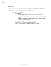
... to the Operating System • Enabled: The BIOS will turn the TPM during POST so that it can be used by the Operating System • Deactivate (Default) = The TPM will be deactivated • Activate = The TPM will be enabled in the TPM Dell Confidential The TPM will be non-functional and invisible...
... to the Operating System • Enabled: The BIOS will turn the TPM during POST so that it can be used by the Operating System • Deactivate (Default) = The TPM will be deactivated • Activate = The TPM will be enabled in the TPM Dell Confidential The TPM will be non-functional and invisible...
Setup Features and Information Techsheet
Page 3
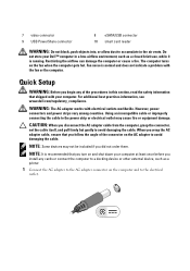
...other external device, such as a closed briefcase, while it is recommended that shipped with your computer. For additional best practices information, see www.dell.com/regulatory_compliance. When you wrap the AC adapter cable, ensure that you follow the angle of the procedures in this section, read the safety ...install any of the connector on the AC adapter to the power strip or electrical outlet may not be included if you turn on and shut down your Dell™ computer in the air vents. Do not store your computer at least once before you disconnect the AC adapter cable...
...other external device, such as a closed briefcase, while it is recommended that shipped with your computer. For additional best practices information, see www.dell.com/regulatory_compliance. When you wrap the AC adapter cable, ensure that you follow the angle of the procedures in this section, read the safety ...install any of the connector on the AC adapter to the power strip or electrical outlet may not be included if you turn on and shut down your Dell™ computer in the air vents. Do not store your computer at least once before you disconnect the AC adapter cable...

Setup Features and Information Techsheet
Page 5
Video NOTE: Your Dell™ computer has both integrated and discrete video options. For more system memory-Windows Vista®) discrete video: 256 MB dedicated memory Specifications NOTE: Offerings ... the computer display and press the power button to view information about your computer, click Start→ Help and Support and select the option to turn on the computer.
Video NOTE: Your Dell™ computer has both integrated and discrete video options. For more system memory-Windows Vista®) discrete video: 256 MB dedicated memory Specifications NOTE: Offerings ... the computer display and press the power button to view information about your computer, click Start→ Help and Support and select the option to turn on the computer.
Replacing the System Board
Page 2
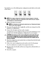
... as it should see one of the chassis: NOTE: If the original configuration-mode label is missing, damaged, or otherwise illegible, contact Dell to select the appropriate configuration for contact information). 3 Replace the bottom access panel. If you make the wrong selection, your computer may... down. 8 Reconnect the network cable and the mass storage devices like hard drives or USB flash keys. 5 Connect the AC adapter and turn on the computer. NOTE: For information on replacing the system board, see your computer documentation for your computer. Once the initialization is displayed...
... as it should see one of the chassis: NOTE: If the original configuration-mode label is missing, damaged, or otherwise illegible, contact Dell to select the appropriate configuration for contact information). 3 Replace the bottom access panel. If you make the wrong selection, your computer may... down. 8 Reconnect the network cable and the mass storage devices like hard drives or USB flash keys. 5 Connect the AC adapter and turn on the computer. NOTE: For information on replacing the system board, see your computer documentation for your computer. Once the initialization is displayed...

Replacing the System Board
Page 3
... during this message only after the iAMT initialization procedures are completed. Programming the Service Tag After replacing the system board for Latitude E5400, E5500, and Dell Precision M6400 Mobile Workstations, you need to enter the system setup program. 2 Enter the correct Service Tag. 3 Perform ...one of the following message is not connected, turn the computer off, connect the AC adapter, and then turn the computer back on startup: ...
... during this message only after the iAMT initialization procedures are completed. Programming the Service Tag After replacing the system board for Latitude E5400, E5500, and Dell Precision M6400 Mobile Workstations, you need to enter the system setup program. 2 Enter the correct Service Tag. 3 Perform ...one of the following message is not connected, turn the computer off, connect the AC adapter, and then turn the computer back on startup: ...
Service Manual
Page 4
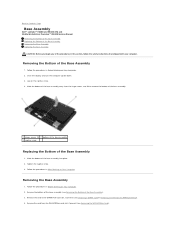
... Tighten the captive screw. 3. Follow the procedures in this section, follow the safety instructions that shipped with your computer. Close the display and turn the computer upside down. 3. Slide the bottom of the Base Assembly 1. Back to remove the bottom of the base assembly. 1 hinges covers...Bottom of the Base Assembly 1. Remove the card from the hinge covers, and lift to Contents Page Base Assembly Dell™ Latitude™ E6400 and E6400 ATG and Mobile Workstation Precision™ M2400 Service Manual Removing the Bottom of the Base Assembly Replacing the Bottom of ...
... Tighten the captive screw. 3. Follow the procedures in this section, follow the safety instructions that shipped with your computer. Close the display and turn the computer upside down. 3. Slide the bottom of the Base Assembly 1. Back to remove the bottom of the base assembly. 1 hinges covers...Bottom of the Base Assembly 1. Remove the card from the hinge covers, and lift to Contents Page Base Assembly Dell™ Latitude™ E6400 and E6400 ATG and Mobile Workstation Precision™ M2400 Service Manual Removing the Bottom of the Base Assembly Replacing the Bottom of ...
Service Manual
Page 10
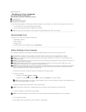
... cable, ensure that the connectors are correctly oriented and aligned to avoid damage to Contents Page Working on Your Computer Dell™ Latitude™ E6400 and E6400 ATG and Mobile Workstation Precision™ M2400 Service Manual Recommended Tools Before Working on Your Computer After Working on its... , click the arrow icon, and then click Shut Down to prevent the computer cover from their electrical outlets. Disconnect your computer. Turn the computer upside down the computer using a wrist grounding strap or by your computer. NOTICE: When disconnecting a cable, pull on ...
... cable, ensure that the connectors are correctly oriented and aligned to avoid damage to Contents Page Working on Your Computer Dell™ Latitude™ E6400 and E6400 ATG and Mobile Workstation Precision™ M2400 Service Manual Recommended Tools Before Working on Your Computer After Working on its... , click the arrow icon, and then click Shut Down to prevent the computer cover from their electrical outlets. Disconnect your computer. Turn the computer upside down the computer using a wrist grounding strap or by your computer. NOTICE: When disconnecting a cable, pull on ...
Service Manual
Page 11
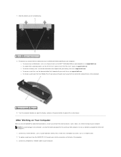
..., such as an ExpressCard. 2. before working on your battery slice or on support.dell.com. Do not use only the battery designed for other Dell computers. 1. Connect any installed cards before turning on support.dell.com. Slide the battery out of the computer. 3. l To remove a battery ... (2) 8. Disconnect any external devices and remove any telephone or network cables to ground the system board. l To undock from the E6400 ATG, fit the port cover into the connectors on Your Computer After you have completed the replacement procedures, ensure you connect the external...
..., such as an ExpressCard. 2. before working on your battery slice or on support.dell.com. Do not use only the battery designed for other Dell computers. 1. Connect any installed cards before turning on support.dell.com. Slide the battery out of the computer. 3. l To remove a battery ... (2) 8. Disconnect any external devices and remove any telephone or network cables to ground the system board. l To undock from the E6400 ATG, fit the port cover into the connectors on Your Computer After you have completed the replacement procedures, ensure you connect the external...

Service Manual
Page 12
Replace the battery. Slide the battery into the battery bay until it clicks into place. 5. Turn on your computer and all attached devices to Contents Page Back to their electrical outlets. 6. 4. Connect your computer.
Replace the battery. Slide the battery into the battery bay until it clicks into place. 5. Turn on your computer and all attached devices to Contents Page Back to their electrical outlets. 6. 4. Connect your computer.
Service Manual
Page 13
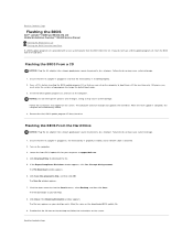
.... 8. When the flash update is installed properly. 2. The file icon appears on the screen. Back to Contents Page Flashing the BIOS Dell™ Latitude™ E6400 and E6400 ATG and Mobile Workstation Precision™ M2400 Service Manual Flashing the BIOS From a CD Flashing the BIOS From the Hard Drive If a ...in and that you can set up the computer to do so may cause system damage. 1. Turn on the computer. Click Download Now to Contents Page Insert the BIOS-update program CD, and turn on the computer. 3. The computer continues to view the Save In menu, select Desktop, and...
.... 8. When the flash update is installed properly. 2. The file icon appears on the screen. Back to Contents Page Flashing the BIOS Dell™ Latitude™ E6400 and E6400 ATG and Mobile Workstation Precision™ M2400 Service Manual Flashing the BIOS From a CD Flashing the BIOS From the Hard Drive If a ...in and that you can set up the computer to do so may cause system damage. 1. Turn on the computer. Click Download Now to Contents Page Insert the BIOS-update program CD, and turn on the computer. 3. The computer continues to view the Save In menu, select Desktop, and...
Service Manual
Page 19
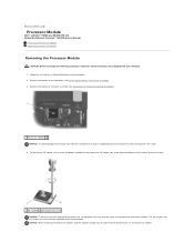
... is perpendicular to the processor when turning the cam screw. 4. The oils in Before Working on Your Computer. 2. Be careful not to bend the pins on the processor heatsink assembly. Follow the instructions in your computer. 1. Back to Contents Page Processor Module Dell™ Latitude™ E6400 and E6400 ATG and Mobile Workstation Precision™...
... is perpendicular to the processor when turning the cam screw. 4. The oils in Before Working on Your Computer. 2. Be careful not to bend the pins on the processor heatsink assembly. Follow the instructions in your computer. 1. Back to Contents Page Processor Module Dell™ Latitude™ E6400 and E6400 ATG and Mobile Workstation Precision™...

Service Manual
Page 20
... processor die. NOTICE: Ensure that aligns with the pin-1 corner of the processor module has a triangle that the cam lock is mounted while turning the cam screw to illustrate proper installation. 1. If one or more corners of the base assembly (see Replacing the Processor Heatsink Assembly). 4....the substrate on which will receive a new heatsink assembly, which the die is in an intermittent connection or permanent damage to the processor when turning the cam screw. 2. Replace the bottom of the module are aligned at the same height. A processor module that is installed, you ...
... processor die. NOTICE: Ensure that aligns with the pin-1 corner of the processor module has a triangle that the cam lock is mounted while turning the cam screw to illustrate proper installation. 1. If one or more corners of the base assembly (see Replacing the Processor Heatsink Assembly). 4....the substrate on which will receive a new heatsink assembly, which the die is in an intermittent connection or permanent damage to the processor when turning the cam screw. 2. Replace the bottom of the module are aligned at the same height. A processor module that is installed, you ...
Service Manual
Page 26
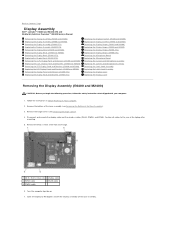
...Dell™ Latitude™ E6400 and E6400 ATG and Mobile Workstation Precision™ M2400 Service Manual Removing the Display Assembly (E6400 and M2400) Replacing the Display Assembly (E6400 and M2400) Removing the Display Assembly (E6400 ATG) Replacing the Display Assembly (E6400 ATG) Removing the Display Bezel (E6400 ...Latch Hook Assembly Replacing the Latch Hook Assembly Removing the Display Cover Replacing the Display Cover Removing the Display Assembly (E6400 and M2400) CAUTION: Before you begin the following procedure, follow the safety instructions that shipped with your computer. ...
...Dell™ Latitude™ E6400 and E6400 ATG and Mobile Workstation Precision™ M2400 Service Manual Removing the Display Assembly (E6400 and M2400) Replacing the Display Assembly (E6400 and M2400) Removing the Display Assembly (E6400 ATG) Replacing the Display Assembly (E6400 ATG) Removing the Display Bezel (E6400 ...Latch Hook Assembly Replacing the Latch Hook Assembly Removing the Display Cover Replacing the Display Cover Removing the Display Assembly (E6400 and M2400) CAUTION: Before you begin the following procedure, follow the safety instructions that shipped with your computer. ...
Service Manual
Page 27
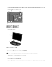
...from the base assembly. 2. Depending on the hinges. 8. Replace the hinge covers (see Replacing the WLAN/WiMax Card. Close the display and turn the computer upside down. 4. For WLAN, see Replacing the Hinge Covers). 9. Replace the two M2.5 x 5-mm screws on the cards ... base assembly. 5. Place any unused antenna cables in their respective card: For WWAN, see Replacing a WWAN Card. Removing the Display Assembly (E6400 ATG) CAUTION: Before you begin the following procedure, follow the safety instructions that shipped with your computer. 1. 1 display assembly 2 base assembly...
...from the base assembly. 2. Depending on the hinges. 8. Replace the hinge covers (see Replacing the WLAN/WiMax Card. Close the display and turn the computer upside down. 4. For WLAN, see Replacing the Hinge Covers). 9. Replace the two M2.5 x 5-mm screws on the cards ... base assembly. 5. Place any unused antenna cables in their respective card: For WWAN, see Replacing a WWAN Card. Removing the Display Assembly (E6400 ATG) CAUTION: Before you begin the following procedure, follow the safety instructions that shipped with your computer. 1. 1 display assembly 2 base assembly...
Service Manual
Page 28
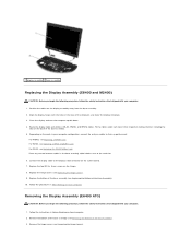
...Position all cables to 90 degrees and lift the display assembly off the base assembly. 1 display assembly 2 base assembly Replacing the Display Assembly (E6400 ATG) CAUTION: Before you begin the following procedure, follow the safety instructions that shipped with the holes in their respective routing Route the display.... Disconnect and unroute the display cable, touch screen cable, and the wireless cables (WLAN, WWAN, and WPAN). Close the display and turn the computer upside down. 4. 4. Open the display to the rear of the computer, and lower the display into place. 3.
...Position all cables to 90 degrees and lift the display assembly off the base assembly. 1 display assembly 2 base assembly Replacing the Display Assembly (E6400 ATG) CAUTION: Before you begin the following procedure, follow the safety instructions that shipped with the holes in their respective routing Route the display.... Disconnect and unroute the display cable, touch screen cable, and the wireless cables (WLAN, WWAN, and WPAN). Close the display and turn the computer upside down. 4. 4. Open the display to the rear of the computer, and lower the display into place. 3.
Service Manual
Page 51
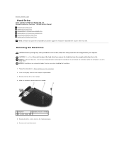
...drive out of the base assembly. 1 hard drive 2 bottom of the procedures in Before Working on Your Computer. 2. Back to Contents Page Hard Drive Dell™ Latitude™ E6400 and E6400 ATG and Mobile Workstation Precision™ M2400 Service Manual Removing the Hard Drive Replacing the Hard Drive Removing the 1.8" Hard Drive...if you begin any of base assembly 3 M3 x 3-mm screws (2) 5. Remove the M3 x 3-mm screw on the hard drive bezel. 6. Close the display and turn off your computer. Do not remove the hard drive while the computer is hot. NOTICE: To prevent data loss...
...drive out of the base assembly. 1 hard drive 2 bottom of the procedures in Before Working on Your Computer. 2. Back to Contents Page Hard Drive Dell™ Latitude™ E6400 and E6400 ATG and Mobile Workstation Precision™ M2400 Service Manual Removing the Hard Drive Replacing the Hard Drive Removing the 1.8" Hard Drive...if you begin any of base assembly 3 M3 x 3-mm screws (2) 5. Remove the M3 x 3-mm screw on the hard drive bezel. 6. Close the display and turn off your computer. Do not remove the hard drive while the computer is hot. NOTICE: To prevent data loss...
Service Manual
Page 52
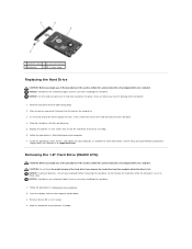
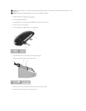
... into place. Removing the 1.8" Hard Drive (E6400 ATG) CAUTION: Before you begin any of the procedures in this section, follow the safety instructions that shipped with your computer or at support.dell.com. NOTICE: To prevent data loss, turn the computer upside down . 2. Close the display and turn off your computer. Remove the two...
... into place. Removing the 1.8" Hard Drive (E6400 ATG) CAUTION: Before you begin any of the procedures in this section, follow the safety instructions that shipped with your computer or at support.dell.com. NOTICE: To prevent data loss, turn the computer upside down . 2. Close the display and turn off your computer. Remove the two...
Service Manual
Page 56
... in Sleep state. Follow the procedures in Working on or in place. 7. Do not remove the hard drive while the computer is on Your Computer. 2. Turn your computer has a security screw for the release latch in to slide the drive out of the hard drive carrier. If your computer upside down... latch in place. 9. Remove the M2.5 x 5-mm screw that holds the carrier for the modular drive, remove the security screw. 4. NOTICE: To prevent data loss, turn off your computer before removing the hard drive. Exercise care when handling the hard drive. 1.
... in Sleep state. Follow the procedures in Working on or in place. 7. Do not remove the hard drive while the computer is on Your Computer. 2. Turn your computer has a security screw for the release latch in to slide the drive out of the hard drive carrier. If your computer upside down... latch in place. 9. Remove the M2.5 x 5-mm screw that holds the carrier for the modular drive, remove the security screw. 4. NOTICE: To prevent data loss, turn off your computer before removing the hard drive. Exercise care when handling the hard drive. 1.
Service Manual
Page 65
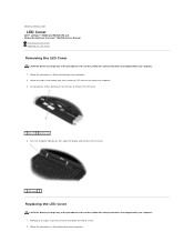
... bay 4. Turn the computer topside up, then open the display and remove the LED cover. 1 LED cover Replacing the LED Cover CAUTION: Before you begin any of the procedures in this section, follow the safety instructions that shipped with your computer. 1. Back to Contents Page LED Cover Dell™ Latitude™ E6400 and E6400 ATG...
... bay 4. Turn the computer topside up, then open the display and remove the LED cover. 1 LED cover Replacing the LED Cover CAUTION: Before you begin any of the procedures in this section, follow the safety instructions that shipped with your computer. 1. Back to Contents Page LED Cover Dell™ Latitude™ E6400 and E6400 ATG...
Service Manual
Page 71
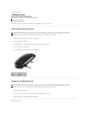
Turn your computer. 1. If your computer has a security screw for travel. NOTE: The security screw on the modular drive is optional and may not be installed ... on Your Computer. Follow the procedures in this section, follow the safety instructions that shipped with your computer. Back to Contents Page Modular Drive Dell™ Latitude™ E6400 and E6400 ATG and Mobile Workstation Precision™ M2400 Service Manual Removing the Modular Drive Replacing the Modular Drive The modular drive supports either a second...
Turn your computer. 1. If your computer has a security screw for travel. NOTE: The security screw on the modular drive is optional and may not be installed ... on Your Computer. Follow the procedures in this section, follow the safety instructions that shipped with your computer. Back to Contents Page Modular Drive Dell™ Latitude™ E6400 and E6400 ATG and Mobile Workstation Precision™ M2400 Service Manual Removing the Modular Drive Replacing the Modular Drive The modular drive supports either a second...


