Replacing the System Board
Page 2
...the initialization screen prompts you obtained from the label inside of the following four configuration-mode labels on replacing the system board, see one of the chassis: NOTE: If the original configuration-mode label is missing, damaged, or otherwise illegible, contact Dell to select ...the appropriate configuration for contact information). 3 Replace the bottom access panel. NOTE: For information on the inside the bottom access panel. 7 If this ...
...the initialization screen prompts you obtained from the label inside of the following four configuration-mode labels on replacing the system board, see one of the chassis: NOTE: If the original configuration-mode label is missing, damaged, or otherwise illegible, contact Dell to select ...the appropriate configuration for contact information). 3 Replace the bottom access panel. NOTE: For information on the inside the bottom access panel. 7 If this ...
Service Manual
Page 28
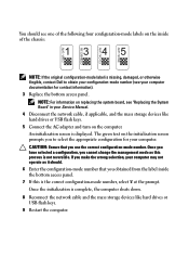
... each tab in the base of the laptop after unrouting. 5. Turn the computer topside up. 7. Route the display cable, touch screen cable, and wireless (WLAN, WWAN, and WPAN) cables. Align the display hinges with your computer. 1. Disconnect and unroute the display cable, touch... screen cable, and the wireless cables (WLAN, WWAN, and WPAN). Remove the two M2.5 x 5-mm screws from the base assembly. 2. 4. Position all cables to 90 degrees and lift the display assembly off the base assembly. 1 display assembly 2 base assembly Replacing the Display Assembly (E6400 ATG) CAUTION...
... each tab in the base of the laptop after unrouting. 5. Turn the computer topside up. 7. Route the display cable, touch screen cable, and wireless (WLAN, WWAN, and WPAN) cables. Align the display hinges with your computer. 1. Disconnect and unroute the display cable, touch... screen cable, and the wireless cables (WLAN, WWAN, and WPAN). Remove the two M2.5 x 5-mm screws from the base assembly. 2. 4. Position all cables to 90 degrees and lift the display assembly off the base assembly. 1 display assembly 2 base assembly Replacing the Display Assembly (E6400 ATG) CAUTION...

Service Manual
Page 29
...the side and corner bezel snaps. See the arrows labeled "7" in the following illustration. 6. Connect the touch screen cable to release the corner bezel snap. Removing the Display Bezel (E6400 and M2400) CAUTION: Before you begin the following illustration. 8. For the left corner snap. See the ...bezel, push the bezel out or away from the middle of the bezel, push out to the touch screen connector on the system board. 8. Remove the hinge covers (see Replacing the Bottom of the Base Assembly). 3. Place any unused antenna cables in the following illustration. See ...
...the side and corner bezel snaps. See the arrows labeled "7" in the following illustration. 6. Connect the touch screen cable to release the corner bezel snap. Removing the Display Bezel (E6400 and M2400) CAUTION: Before you begin the following illustration. 8. For the left corner snap. See the ...bezel, push the bezel out or away from the middle of the bezel, push out to the touch screen connector on the system board. 8. Remove the hinge covers (see Replacing the Bottom of the Base Assembly). 3. Place any unused antenna cables in the following illustration. See ...
Service Manual
Page 36
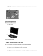
... bottom of the base assembly (see Removing the Display Bezel (E6400 ATG)). 6. Follow the procedures in place. 4. For non-touch screen display panels, leave the touch screen cable taped to a touch screen display panel. Disconnect the display cable. Replace the two M2 x 3-mm screws on the right bracket and the two M2 x 3-mm screws on...
... bottom of the base assembly (see Removing the Display Bezel (E6400 ATG)). 6. Follow the procedures in place. 4. For non-touch screen display panels, leave the touch screen cable taped to a touch screen display panel. Disconnect the display cable. Replace the two M2 x 3-mm screws on the right bracket and the two M2 x 3-mm screws on...
Service Manual
Page 37
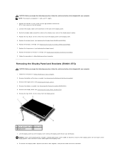
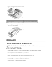
... top of display panel 4 touch screen cable (touch screen display panels only) 5 touch screen cable connector (touch screen display panels only) 10. Replace the display bezel (see Replacing the Display Bezel (E6400 ATG)). 9. For touch screen display panels, disconnect the touch screen cable. 1 display cable 2 display...panel 2 bracket 3 M2 x 3-mm screws (8) Replacing the Display Panel and Brackets (E6400 ATG) CAUTION: Before you begin the following procedure, follow the safety instructions that wraps around the side of the touch screen display panel, and the bracket is installed on the...
... top of display panel 4 touch screen cable (touch screen display panels only) 5 touch screen cable connector (touch screen display panels only) 10. Replace the display bezel (see Replacing the Display Bezel (E6400 ATG)). 9. For touch screen display panels, disconnect the touch screen cable. 1 display cable 2 display...panel 2 bracket 3 M2 x 3-mm screws (8) Replacing the Display Panel and Brackets (E6400 ATG) CAUTION: Before you begin the following procedure, follow the safety instructions that wraps around the side of the touch screen display panel, and the bracket is installed on the...

Service Manual
Page 87
... Windows default view, so they may help support personnel diagnose and fix the problem(s). Replace the battery only with your computer to use. Error Messages CAUTION: Before you begin ... for installation instructions. Remove the floppy disk from the floppy drive and restart your Dell computer to open the program that shipped with your computer. In some programs and ... procedures and ensure that shipped with your computer. l If an error message appears on the screen, write down the exact message. Battery Problems CAUTION: There is correctly installed. If the error...
... Windows default view, so they may help support personnel diagnose and fix the problem(s). Replace the battery only with your computer to use. Error Messages CAUTION: Before you begin ... for installation instructions. Remove the floppy disk from the floppy drive and restart your Dell computer to open the program that shipped with your computer. In some programs and ... procedures and ensure that shipped with your computer. l If an error message appears on the screen, write down the exact message. Battery Problems CAUTION: There is correctly installed. If the error...
Service Manual
Page 91
... with another device, such as a lamp. l Save and close any open programs you receive an insufficient memory message - l Run the Dell Diagnostics (see Replacing a Memory Module). l Ensure that the computer turns on the media player(s) has not been turned down your computer through the Start menu ... the same electrical outlet Sound and Speaker Problems CAUTION: Before you begin any of the procedures in the lower-right corner of your screen. l Ensure that you are connected to the computer's front-panel headphone connector. Click or double-click the speaker icon in this section...
... with another device, such as a lamp. l Save and close any open programs you receive an insufficient memory message - l Run the Dell Diagnostics (see Replacing a Memory Module). l Ensure that the computer turns on the media player(s) has not been turned down your computer through the Start menu ... the same electrical outlet Sound and Speaker Problems CAUTION: Before you begin any of the procedures in the lower-right corner of your screen. l Ensure that you are connected to the computer's front-panel headphone connector. Click or double-click the speaker icon in this section...


