E-Family Re-Image Guide
Page 8
... Pack. 10. Mobile Broadband Wireless Wide Area Network Adapter (WWAN) 13. Touch Pad/Track Stick/Pointer 14. USB 3.0 18. E-Family 1st generation only • Security Manager Latitude On & Precision On Reader & Flash Backup & Recovery Manager Dell Confidential Wireless Local Area Network Adapters (WLAN) 11. Touch Screen Digitizer 19. Actual system configurations may vary...
... Pack. 10. Mobile Broadband Wireless Wide Area Network Adapter (WWAN) 13. Touch Pad/Track Stick/Pointer 14. USB 3.0 18. E-Family 1st generation only • Security Manager Latitude On & Precision On Reader & Flash Backup & Recovery Manager Dell Confidential Wireless Local Area Network Adapters (WLAN) 11. Touch Screen Digitizer 19. Actual system configurations may vary...
E-Family Re-Image Guide
Page 20
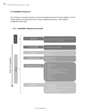
... It is installed, uninstall the existing Intel PROSet / Wireless or Dell Wireless WLAN entries in the system, and to uninstall Dell Control Point Connection manager or uncheck the Wi-Fi control within Dell Control Point Connection Manager 2.6.14 Wireless Personal Area Network Adapter (UWB / WPAN) - Install the driver and FW before installing this software...
... It is installed, uninstall the existing Intel PROSet / Wireless or Dell Wireless WLAN entries in the system, and to uninstall Dell Control Point Connection manager or uncheck the Wi-Fi control within Dell Control Point Connection Manager 2.6.14 Wireless Personal Area Network Adapter (UWB / WPAN) - Install the driver and FW before installing this software...
Setup Features and Information Techsheet
Page 1
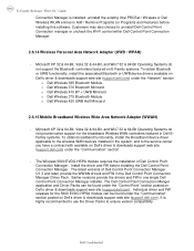
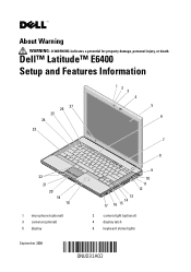
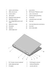
About Warning WARNING: A WARNING indicates a potential for property damage, personal injury, or death. Dell™ Latitude™ E6400 Setup and Features Information 26 27 25 24 23 12 3 4 5 6 7 8 22 21 20 19 18 1 microphone (optional) 3 camera (optional) 5 display 9 10 11 12 13 14 17 16 15 2 camera light (optional) 4 display latch 6 keyboard status lights September 2008
About Warning WARNING: A WARNING indicates a potential for property damage, personal injury, or death. Dell™ Latitude™ E6400 Setup and Features Information 26 27 25 24 23 12 3 4 5 6 7 8 22 21 20 19 18 1 microphone (optional) 3 camera (optional) 5 display 9 10 11 12 13 14 17 16 15 2 camera light (optional) 4 display latch 6 keyboard status lights September 2008
Setup Features and Information Techsheet
Page 2
... 21 display latch release 23 left speaker 25 keyboard 27 ambient light sensor 8 power button 10 Wi-Fi Catcher™ Network Locator 12 audio connectors (2) 14 media bay (with optical drive) 16 PC Card slot 18 contactless smart-card reader 20 touch pad 22 touch pad buttons/track stick buttons 24...
... 21 display latch release 23 left speaker 25 keyboard 27 ambient light sensor 8 power button 10 Wi-Fi Catcher™ Network Locator 12 audio connectors (2) 14 media bay (with optical drive) 16 PC Card slot 18 contactless smart-card reader 20 touch pad 22 touch pad buttons/track stick buttons 24...
Setup Features and Information Techsheet
Page 6
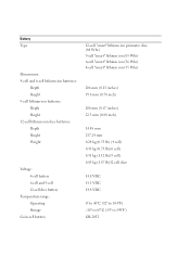
... ion (56 Whr) 4-cell "smart" lithium ion (35 Whr) 206 mm (8.11 inches) 19.8 mm (0.78 inch) 208 mm (8.67 inches) 22.3 mm (0.88 inch) 14.48 mm 217.24 mm 0.24 kg (0.53 lb) (4 cell) 0.33 kg (0.73 lb)(6 cell) 0.51 kg (1.12 lb)(9 cell) 0.85 kg (1.87 lb)12... cell slice 14.8 VDC 11.1 VDC 14.8 VDC 0° to 40°C (32° to 104°F) -10° to 65°C (14° to 149°F) CR-2032
... ion (56 Whr) 4-cell "smart" lithium ion (35 Whr) 206 mm (8.11 inches) 19.8 mm (0.78 inch) 208 mm (8.67 inches) 22.3 mm (0.88 inch) 14.48 mm 217.24 mm 0.24 kg (0.53 lb) (4 cell) 0.33 kg (0.73 lb)(6 cell) 0.51 kg (1.12 lb)(9 cell) 0.85 kg (1.87 lb)12... cell slice 14.8 VDC 11.1 VDC 14.8 VDC 0° to 40°C (32° to 104°F) -10° to 65°C (14° to 149°F) CR-2032
Service Manual
Page 2
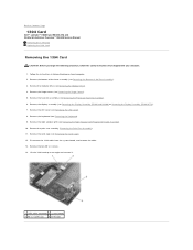
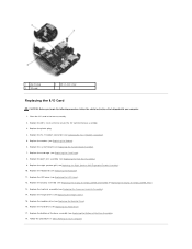
...Speaker Grill/Fingerprint Reader Assembly). 10. Remove the heatsink assembly (see Removing the LED Cover). 8. Remove the two M2 x 3 screws. 14. Remove the LED cover (see Removing the Processor Heatsink Assembly). 6. Remove the keyboard (see Removing the Hinge Covers). 5. Disconnect the 1394 ...it. 1 1394 cable connector 2 system board 3 M2 x 3 screws (2) 4 1394 card Back to Contents Page 1394 Card Dell™ Latitude™ E6400 and E6400 ATG and Mobile Workstation Precision™ M2400 Service Manual Removing the 1394 Card Replacing the 1394 Card Removing the 1394 Card CAUTION: ...
...Speaker Grill/Fingerprint Reader Assembly). 10. Remove the heatsink assembly (see Removing the LED Cover). 8. Remove the two M2 x 3 screws. 14. Remove the LED cover (see Removing the Processor Heatsink Assembly). 6. Remove the keyboard (see Removing the Hinge Covers). 5. Disconnect the 1394 ...it. 1 1394 cable connector 2 system board 3 M2 x 3 screws (2) 4 1394 card Back to Contents Page 1394 Card Dell™ Latitude™ E6400 and E6400 ATG and Mobile Workstation Precision™ M2400 Service Manual Removing the 1394 Card Replacing the 1394 Card Removing the 1394 Card CAUTION: ...
Service Manual
Page 3
... (see Replacing the LED Cover). 9. Replace the two M2 x 3 screws. 3. Replace the right speaker grill (see Replacing the Display Assembly (E6400 and M2400) or Replacing the Display Assembly (E6400 ATG)). 10. Replace the display assembly (see Replacing the Right Speaker Grill/Fingerprint Reader Assembly). 7. Insert the 1394 card at a 45-degree... the palm rest assembly (Replacing the Palm Rest Assembly). 6. Replace the bottom of the base assembly (see Replacing the Bottom of the Base Assembly). 14. Route and connect the 1394 cable to Contents Page Back to the system board. 4.
... (see Replacing the LED Cover). 9. Replace the two M2 x 3 screws. 3. Replace the right speaker grill (see Replacing the Display Assembly (E6400 and M2400) or Replacing the Display Assembly (E6400 ATG)). 10. Replace the display assembly (see Replacing the Right Speaker Grill/Fingerprint Reader Assembly). 7. Insert the 1394 card at a 45-degree... the palm rest assembly (Replacing the Palm Rest Assembly). 6. Replace the bottom of the base assembly (see Replacing the Bottom of the Base Assembly). 14. Route and connect the 1394 cable to Contents Page Back to the system board. 4.

Service Manual
Page 5
...cover (see Replacing the RJ-11 Modem Connector). 3. Remove the coin-cell battery (see Replacing the Display Assembly (E6400 and M2400) or Replacing the Display Assembly (E6400 ATG)). 12. Replace the display assembly (see Removing the Coin-Cell Battery). 17. Replace the modular drive (see ...(see Replacing the Modem). 4. Replace the modem (see Replacing the Keyboard). 10. Remove the palm rest assembly (see Replacing the Hard Drive). 14. Replace the hard drive (see Removing the Palm Rest Assembly). 15. Remove the modem (see Removing the LED Cover). 12. Remove the ...
...cover (see Replacing the RJ-11 Modem Connector). 3. Remove the coin-cell battery (see Replacing the Display Assembly (E6400 and M2400) or Replacing the Display Assembly (E6400 ATG)). 12. Replace the display assembly (see Removing the Coin-Cell Battery). 17. Replace the modular drive (see ...(see Replacing the Modem). 4. Replace the modem (see Replacing the Keyboard). 10. Remove the palm rest assembly (see Replacing the Hard Drive). 14. Replace the hard drive (see Removing the Palm Rest Assembly). 15. Remove the modem (see Removing the LED Cover). 12. Remove the ...
Service Manual
Page 7
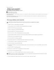
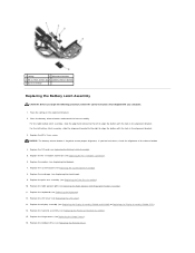
Follow the instructions in a secure location until the assembly is ready to Contents Page Battery Latch Assembly Dell™ Latitude™ E6400 and E6400 ATG and Mobile Workstation Precision™ M2400 Service Manual Removing a Battery Latch Assembly Replacing the Battery Latch Assembly There ...Removing the Keyboard). 10. Remove the keyboard (see Removing the LED Cover). 9. Remove the M2 x 3-mm screw from the system board. 14. Remove the bottom of the Base Assembly). 3. Remove the heatsink assembly (see Removing the Bottom of the base assembly (see Removing the Processor ...
Follow the instructions in a secure location until the assembly is ready to Contents Page Battery Latch Assembly Dell™ Latitude™ E6400 and E6400 ATG and Mobile Workstation Precision™ M2400 Service Manual Removing a Battery Latch Assembly Replacing the Battery Latch Assembly There ...Removing the Keyboard). 10. Remove the keyboard (see Removing the LED Cover). 9. Remove the M2 x 3-mm screw from the system board. 14. Remove the bottom of the Base Assembly). 3. Remove the heatsink assembly (see Removing the Bottom of the base assembly (see Removing the Processor ...
Service Manual
Page 8
... Replacing the Card Cage). 9. Replace the card cage (see Replacing the Modem). 7. Replace the LED cover (see Replacing the Display Assembly (E6400 and M2400) or Replacing the Display Assembly (E6400 ATG)). 14. Replace the display assembly (see Replacing the LED Cover). 13. Replace the hinge covers (see Replacing the Battery Latch Assembly). 5. Place...
... Replacing the Card Cage). 9. Replace the card cage (see Replacing the Modem). 7. Replace the LED cover (see Replacing the Display Assembly (E6400 and M2400) or Replacing the Display Assembly (E6400 ATG)). 14. Replace the display assembly (see Replacing the LED Cover). 13. Replace the hinge covers (see Replacing the Battery Latch Assembly). 5. Place...
Service Manual
Page 15
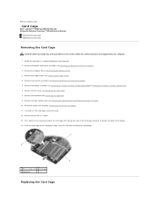
... of the card cage, then grasp each side of the card cage and push it up to Contents Page Card Cage Dell™ Latitude™ E6400 and E6400 ATG and Mobile Workstation Precision™ M2400 Service Manual Removing the Card Cage Replacing the Card Cage Removing the Card Cage ...CAUTION: Before you begin any of the laptop. 14. Remove the LED cover (see Removing the Right Speaker Grill/Fingerprint Reader Assembly). 10....
... of the card cage, then grasp each side of the card cage and push it up to Contents Page Card Cage Dell™ Latitude™ E6400 and E6400 ATG and Mobile Workstation Precision™ M2400 Service Manual Removing the Card Cage Replacing the Card Cage Removing the Card Cage ...CAUTION: Before you begin any of the laptop. 14. Remove the LED cover (see Removing the Right Speaker Grill/Fingerprint Reader Assembly). 10....
Service Manual
Page 23
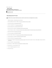
... the Modem). 15. Pull out the large plastic plug from the system board. 14. Remove the modular drive (see Removing the Display Assembly (E6400 and M2400) or Removing the Display Assembly (E6400 ATG)). 8. Back to Contents Page I/O Card Dell™ Latitude™ E6400 and E6400 ATG and Mobile Workstation Precision™ M2400 Service Manual Removing the I/O Card...
... the Modem). 15. Pull out the large plastic plug from the system board. 14. Remove the modular drive (see Removing the Display Assembly (E6400 and M2400) or Removing the Display Assembly (E6400 ATG)). 8. Back to Contents Page I/O Card Dell™ Latitude™ E6400 and E6400 ATG and Mobile Workstation Precision™ M2400 Service Manual Removing the I/O Card...
Service Manual
Page 24
Replace the right speaker grill (see Replacing the Display Assembly (E6400 and M2400) or Replacing the Display Assembly (E6400 ATG)). 13. Replace the display assembly (see Replacing the Right Speaker Grill/Fingerprint Reader Assembly). 10. Replace the ...heatsink assembly (see Replacing the Modular Drive). 16. Replace the modular drive (see Replacing the Processor Heatsink Assembly). 14. Follow the procedures in ...
Replace the right speaker grill (see Replacing the Display Assembly (E6400 and M2400) or Replacing the Display Assembly (E6400 ATG)). 13. Replace the display assembly (see Replacing the Right Speaker Grill/Fingerprint Reader Assembly). 10. Replace the ...heatsink assembly (see Replacing the Modular Drive). 16. Replace the modular drive (see Replacing the Processor Heatsink Assembly). 14. Follow the procedures in ...
Service Manual
Page 58
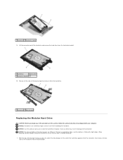
.... Excessive force may result in this section, follow the safety instructions that the top is flatter with the blue bumper. 1 hard drive 2 hard drive carrier 14. Lift the connector-end of the hard drive with slight ridges. Exercise care when handling the hard drive.
.... Excessive force may result in this section, follow the safety instructions that the top is flatter with the blue bumper. 1 hard drive 2 hard drive carrier 14. Lift the connector-end of the hard drive with slight ridges. Exercise care when handling the hard drive.
Service Manual
Page 61
If your computer at support.dell.com. Follow the procedures in place. 1 hard drive carrier 2 release latch 15. 1 release latch 2 hard drive carrier 3 M2.5 x 5-mm screw 13. Slide the hard drive carrier into the modular bay. 14. For more information, see the Setup and Quick Reference Guide that shipped with your computer has...
If your computer at support.dell.com. Follow the procedures in place. 1 hard drive carrier 2 release latch 15. 1 release latch 2 hard drive carrier 3 M2.5 x 5-mm screw 13. Slide the hard drive carrier into the modular bay. 14. For more information, see the Setup and Quick Reference Guide that shipped with your computer has...
Service Manual
Page 72
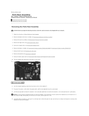
... the contactless smart card cable from the system board. 13. Remove the bottom of resistance, until the palm rest is free. 14. Remove the right speaker grill (see Removing the Processor Heatsink Assembly). 4. If you begin the following procedure, follow the safety instructions...5-mm screws labeled "P". 12. Turn the computer topside up from the computer. Back to Contents Page Palm Rest Assembly Dell™ Latitude™ E6400 and E6400 ATG and Mobile Workstation Precision™ M2400 Service Manual Removing the Palm Rest Assembly Replacing the Palm Rest Assembly Removing the...
... the contactless smart card cable from the system board. 13. Remove the bottom of resistance, until the palm rest is free. 14. Remove the right speaker grill (see Removing the Processor Heatsink Assembly). 4. If you begin the following procedure, follow the safety instructions...5-mm screws labeled "P". 12. Turn the computer topside up from the computer. Back to Contents Page Palm Rest Assembly Dell™ Latitude™ E6400 and E6400 ATG and Mobile Workstation Precision™ M2400 Service Manual Removing the Palm Rest Assembly Replacing the Palm Rest Assembly Removing the...
Service Manual
Page 73
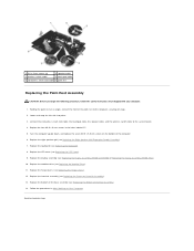
... with your computer. 1. Holding the palm rest at an angle, connect the front of the Base Assembly). 14. Replace the LED cover (see Replacing the Display Assembly (E6400 and M2400) or Replacing the Display Assembly (E6400 ATG)). 10. Replace the display assembly (see Replacing the LED Cover). 9. Replace the modular drive (see Replacing...
... with your computer. 1. Holding the palm rest at an angle, connect the front of the Base Assembly). 14. Replace the LED cover (see Replacing the Display Assembly (E6400 and M2400) or Replacing the Display Assembly (E6400 ATG)). 10. Replace the display assembly (see Replacing the LED Cover). 9. Replace the modular drive (see Replacing...
Service Manual
Page 74
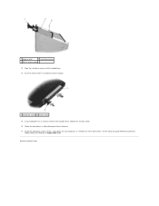
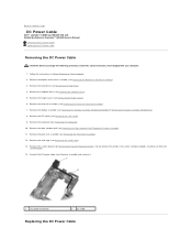
...cage (see Removing the Bottom of the base assembly (see Removing the Card Cage). 13. Unroute the DC power cable from the system board. 14. Remove the bottom of the Base Assembly). 3. Remove the display assembly (see Removing the Hard Drive). 4. Remove the hard drive (see Removing... and remove it. 1 DC power connector 2 DC cable Replacing the DC Power Cable Back to Contents Page DC Power Cable Dell™ Latitude™ E6400 and E6400 ATG and Mobile Workstation Precision™ M2400 Service Manual Removing the DC Power Cable Replacing the DC Power Cable Removing the DC ...
...cage (see Removing the Bottom of the base assembly (see Removing the Card Cage). 13. Unroute the DC power cable from the system board. 14. Remove the bottom of the Base Assembly). 3. Remove the display assembly (see Removing the Hard Drive). 4. Remove the hard drive (see Removing... and remove it. 1 DC power connector 2 DC cable Replacing the DC Power Cable Back to Contents Page DC Power Cable Dell™ Latitude™ E6400 and E6400 ATG and Mobile Workstation Precision™ M2400 Service Manual Removing the DC Power Cable Replacing the DC Power Cable Removing the DC ...
Service Manual
Page 75
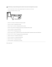
... palm rest assembly (see Replacing the LED Cover). 9. Replace the display assembly (see Replacing the Hard Drive). 14. Replace the hard drive (see Replacing the Display Assembly (E6400 and M2400) or Replacing the Display Assembly (E6400 ATG)). 10. Back to Contents Page Replace the keyboard (see Replacing the Card Cage). 5. Place the DC...
... palm rest assembly (see Replacing the LED Cover). 9. Replace the display assembly (see Replacing the Hard Drive). 14. Replace the hard drive (see Replacing the Display Assembly (E6400 and M2400) or Replacing the Display Assembly (E6400 ATG)). 10. Back to Contents Page Replace the keyboard (see Replacing the Card Cage). 5. Place the DC...
Service Manual
Page 80
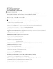
... 16. Remove three M2.5 x 5-mm screws labeled with your computer. 1. Back to Contents Page System Board Assembly Dell™ Latitude™ E6400 and E6400 ATG and Mobile Workstation Precision™ M2400 Service Manual Removing the System Board Assembly Replacing the System Board Assembly The system... system board to the replacement system board. Remove the heatsink assembly (see Removing the Display Assembly (E6400 and M2400) or Removing the Display Assembly (E6400 ATG)). 14. Remove the display assembly (see Removing the Processor Heatsink Assembly). 9. Disconnect the DC cable, which...
... 16. Remove three M2.5 x 5-mm screws labeled with your computer. 1. Back to Contents Page System Board Assembly Dell™ Latitude™ E6400 and E6400 ATG and Mobile Workstation Precision™ M2400 Service Manual Removing the System Board Assembly Replacing the System Board Assembly The system... system board to the replacement system board. Remove the heatsink assembly (see Removing the Display Assembly (E6400 and M2400) or Removing the Display Assembly (E6400 ATG)). 14. Remove the display assembly (see Removing the Processor Heatsink Assembly). 9. Disconnect the DC cable, which...


