Replacing the System Board
Page 2
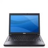
... make the wrong selection, your Service Manual. 4 Disconnect the network cable, if applicable, and the mass storage devices like hard drives or USB flash keys. 9 Restart the computer. NOTE: For information on replacing the system board, see your computer documentation ...for your computer. An initialization screen is missing, damaged, or otherwise illegible, contact Dell to select the appropriate configuration for contact information). 3 Replace the bottom access panel. Once the initialization is the correct configuration-mode...
... make the wrong selection, your Service Manual. 4 Disconnect the network cable, if applicable, and the mass storage devices like hard drives or USB flash keys. 9 Restart the computer. NOTE: For information on replacing the system board, see your computer documentation ...for your computer. An initialization screen is missing, damaged, or otherwise illegible, contact Dell to select the appropriate configuration for contact information). 3 Replace the bottom access panel. Once the initialization is the correct configuration-mode...
Service Manual
Page 1
... may be used by Bluetooth SIG, Inc., and is used in the U.S. Reproduction of Dell Inc.; Dell™ Latitude™ E6400 and E6400 ATG and Mobile Workstation Precision™ M2400 Service Manual Troubleshooting Working on Your Computer Base Assembly Hinge Covers Hard Drive WLAN/WiMax Card WWAN Card WPAN (UWB/BT) Card FCM Fan Processor Heatsink Assembly...
... may be used by Bluetooth SIG, Inc., and is used in the U.S. Reproduction of Dell Inc.; Dell™ Latitude™ E6400 and E6400 ATG and Mobile Workstation Precision™ M2400 Service Manual Troubleshooting Working on Your Computer Base Assembly Hinge Covers Hard Drive WLAN/WiMax Card WWAN Card WPAN (UWB/BT) Card FCM Fan Processor Heatsink Assembly...

Service Manual
Page 5
... the Keyboard). 10. Replace the display assembly (see Replacing the Hard Drive). 14. Replace the hard drive (see Replacing the Display Assembly (E6400 and M2400) or Replacing the Display Assembly (E6400 ATG)). 12. Remove the hard drive (see Removing the Display Assembly (E6400 and M2400) or Removing the Display Assembly (E6400 ATG)). 11. Remove the display assembly (see Removing the...
... the Keyboard). 10. Replace the display assembly (see Replacing the Hard Drive). 14. Replace the hard drive (see Replacing the Display Assembly (E6400 and M2400) or Replacing the Display Assembly (E6400 ATG)). 12. Remove the hard drive (see Removing the Display Assembly (E6400 and M2400) or Removing the Display Assembly (E6400 ATG)). 11. Remove the display assembly (see Removing the...
Service Manual
Page 7
... the safety instructions that are two battery latches, a left battery latch. Remove the hard drive (see Removing the Palm Rest Assembly). 12. Remove the palm rest assembly (see Removing the Hard Drive). 4. Remove the I /O Card). 17. Remove the spring from the alignment bracket... speaker grill (see Removing the Hinge Covers). 6. NOTICE: The spring is ready to Contents Page Battery Latch Assembly Dell™ Latitude™ E6400 and E6400 ATG and Mobile Workstation Precision™ M2400 Service Manual Removing a Battery Latch Assembly Replacing the Battery Latch Assembly There ...
... the safety instructions that are two battery latches, a left battery latch. Remove the hard drive (see Removing the Palm Rest Assembly). 12. Remove the palm rest assembly (see Removing the Hard Drive). 4. Remove the I /O Card). 17. Remove the spring from the alignment bracket... speaker grill (see Removing the Hinge Covers). 6. NOTICE: The spring is ready to Contents Page Battery Latch Assembly Dell™ Latitude™ E6400 and E6400 ATG and Mobile Workstation Precision™ M2400 Service Manual Removing a Battery Latch Assembly Replacing the Battery Latch Assembly There ...

Service Manual
Page 9
Follow the procedures in After Working on Your Computer. 17. Back to Contents Page Replace the hard drive (see Replacing the Bottom of the base assembly (see Replacing the Hard Drive). 18. Replace the bottom of the Base Assembly). 19.
Follow the procedures in After Working on Your Computer. 17. Back to Contents Page Replace the hard drive (see Replacing the Bottom of the base assembly (see Replacing the Hard Drive). 18. Replace the bottom of the Base Assembly). 19.
Service Manual
Page 13
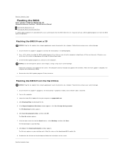
...must enter the system setup program to Contents Page Flashing the BIOS Dell™ Latitude™ E6400 and E6400 ATG and Mobile Workstation Precision™ M2400 Service Manual Flashing the BIOS From a CD Flashing the BIOS From the Hard Drive If a BIOS-update program CD is provided with a new system... board, flash the BIOS from the drive. Click Download Now to view the ...
...must enter the system setup program to Contents Page Flashing the BIOS Dell™ Latitude™ E6400 and E6400 ATG and Mobile Workstation Precision™ M2400 Service Manual Flashing the BIOS From a CD Flashing the BIOS From the Hard Drive If a BIOS-update program CD is provided with a new system... board, flash the BIOS from the drive. Click Download Now to view the ...
Service Manual
Page 23
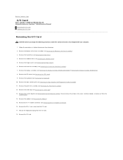
... grill (see Removing the Display Assembly (E6400 and M2400) or Removing the Display Assembly (E6400 ATG)). 8. Remove the palm rest assembly (see Removing the Hard Drive). 4. Remove the M2 x 3-mm screw from the I /O card. Remove the hard drive (see Removing the Palm Rest Assembly). ...Removing the RJ-11 Modem Connector). 16. Remove the modular drive (see Removing the Bottom of the base assembly (see Removing the Modular Drive). 5. Back to Contents Page I/O Card Dell™ Latitude™ E6400 and E6400 ATG and Mobile Workstation Precision™ M2400 Service Manual Removing the...
... grill (see Removing the Display Assembly (E6400 and M2400) or Removing the Display Assembly (E6400 ATG)). 8. Remove the palm rest assembly (see Removing the Hard Drive). 4. Remove the M2 x 3-mm screw from the I /O card. Remove the hard drive (see Removing the Palm Rest Assembly). ...Removing the RJ-11 Modem Connector). 16. Remove the modular drive (see Removing the Bottom of the base assembly (see Removing the Modular Drive). 5. Back to Contents Page I/O Card Dell™ Latitude™ E6400 and E6400 ATG and Mobile Workstation Precision™ M2400 Service Manual Removing the...
Service Manual
Page 24
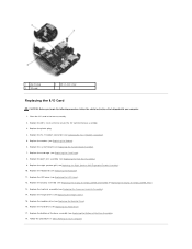
...E6400 ATG)). 13. Replace the card cage (see Replacing the Modular Drive). 16. Replace the modular drive (see Replacing the Card Cage). 8. Replace the RJ-11 modem connector (see Replacing the System Board Assembly). 7. Replace the system board (see Replacing the RJ-11 Modem Connector). 5. Replace the hard drive... (see Replacing the Keyboard). 11. Follow the procedures in the base assembly. 2. Replace the keyboard (see Replacing the Hard Drive). 17. Replace the hinge covers (see Replacing the LED Cover). 12...
...E6400 ATG)). 13. Replace the card cage (see Replacing the Modular Drive). 16. Replace the modular drive (see Replacing the Card Cage). 8. Replace the RJ-11 modem connector (see Replacing the System Board Assembly). 7. Replace the system board (see Replacing the RJ-11 Modem Connector). 5. Replace the hard drive... (see Replacing the Keyboard). 11. Follow the procedures in the base assembly. 2. Replace the keyboard (see Replacing the Hard Drive). 17. Replace the hinge covers (see Replacing the LED Cover). 12...
Service Manual
Page 51
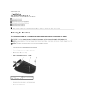
... before removing the hard drive. Removing the Hard Drive CAUTION: Before you remove the hard drive from sources other than Dell. Back to Contents Page Hard Drive Dell™ Latitude™ E6400 and E6400 ATG and Mobile Workstation Precision™ M2400 Service Manual Removing the Hard Drive Replacing the Hard Drive Removing the 1.8" Hard Drive (E6400 ATG) Replacing the 1.8" Hard Drive (E6400 ATG) Removing the Modular Hard Drive Replacing the Modular Hard Drive NOTE: Dell does not guarantee...
... before removing the hard drive. Removing the Hard Drive CAUTION: Before you remove the hard drive from sources other than Dell. Back to Contents Page Hard Drive Dell™ Latitude™ E6400 and E6400 ATG and Mobile Workstation Precision™ M2400 Service Manual Removing the Hard Drive Replacing the Hard Drive Removing the 1.8" Hard Drive (E6400 ATG) Replacing the 1.8" Hard Drive (E6400 ATG) Removing the Modular Hard Drive Replacing the Modular Hard Drive NOTE: Dell does not guarantee...
Service Manual
Page 52
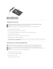
...hard drive with your computer or at support.dell.com. Follow the procedures in Working on Your Computer. 2. Do not remove the hard drive while the computer is hot. NOTICE: Hard drives are extremely fragile. Slide the hard drive out of the bezel, replace the M3 x 3-mm screw that secures the hard drive bezel to slide the hard drive...NOTICE: To prevent data loss, turn the computer upside down . 2. Exercise care when handling the hard drive. 1. Removing the 1.8" Hard Drive (E6400 ATG) CAUTION: Before you begin any of the procedures in this section, follow the safety instructions ...
...hard drive with your computer or at support.dell.com. Follow the procedures in Working on Your Computer. 2. Do not remove the hard drive while the computer is hot. NOTICE: Hard drives are extremely fragile. Slide the hard drive out of the bezel, replace the M3 x 3-mm screw that secures the hard drive bezel to slide the hard drive...NOTICE: To prevent data loss, turn the computer upside down . 2. Exercise care when handling the hard drive. 1. Removing the 1.8" Hard Drive (E6400 ATG) CAUTION: Before you begin any of the procedures in this section, follow the safety instructions ...
Service Manual
Page 53
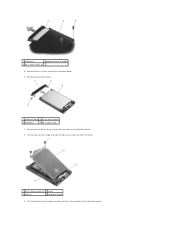
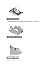
Remove the hard drive bezel. 1 hard drive bezel 2 pin on the hard drive bezel. 6. Remove the two M2.5 x 5-mm screws from the carrier. 1 M2.5 x 5-mm screws (2) 2 cover 3 tabs (2) 4 hard drive carrier 9. Remove the M3 x 3-mm screw on bezel bracket 3 hard drive 4 M3 x 3-mm screw 7. Lift the hard drive up at an angle and slide the tabs on the hard drive carrier. 1 hard drive 2 bottom of the hard drive carrier. 8. Lift the cover up an angle and slide it out from the connector on the cover out from the cover of base assembly 3 M3 x 3-mm screws (2) 5.
Remove the hard drive bezel. 1 hard drive bezel 2 pin on the hard drive bezel. 6. Remove the two M2.5 x 5-mm screws from the carrier. 1 M2.5 x 5-mm screws (2) 2 cover 3 tabs (2) 4 hard drive carrier 9. Remove the M3 x 3-mm screw on bezel bracket 3 hard drive 4 M3 x 3-mm screw 7. Lift the hard drive up at an angle and slide the tabs on the hard drive carrier. 1 hard drive 2 bottom of the hard drive carrier. 8. Lift the cover up an angle and slide it out from the connector on the cover out from the cover of base assembly 3 M3 x 3-mm screws (2) 5.
Service Manual
Page 54
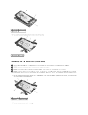
... of the hard drive opposite from the hard drive. 1 hard drive 2 blue bumper Replacing the 1.8" Hard Drive (E6400 ATG) CAUTION: Before you begin any of the blue bumper are extremely fragile. Place the hard drive into place. NOTICE: Hard drives are different. NOTICE: The top and bottom of the procedures in damage to slide the hard drive into the carrier at an angle. 1 hard drive 2 hard drive carrier 3 connector...
... of the hard drive opposite from the hard drive. 1 hard drive 2 blue bumper Replacing the 1.8" Hard Drive (E6400 ATG) CAUTION: Before you begin any of the blue bumper are extremely fragile. Place the hard drive into place. NOTICE: Hard drives are different. NOTICE: The top and bottom of the procedures in damage to slide the hard drive into the carrier at an angle. 1 hard drive 2 hard drive carrier 3 connector...
Service Manual
Page 55
...3 lip on the hard drive carrier. 5. Slide the hard drive into the hole on Your Computer. 11. Connect the hard drive to the connector in After Working on the hard drive. 7. On the other end of the bezel, replace the M3 x 3-mm screw that secure the hard drive to the hard drive. 8. Replace the ...two M3 x 3-mm screws that secures the hard drive bezel to the base assembly. 10. Follow the procedures in the carrier. 1 hard drive 2 hard drive carrier 3 connector 4. For more information, see the ...
...3 lip on the hard drive carrier. 5. Slide the hard drive into the hole on Your Computer. 11. Connect the hard drive to the connector in After Working on the hard drive. 7. On the other end of the bezel, replace the M3 x 3-mm screw that secure the hard drive to the hard drive. 8. Replace the ...two M3 x 3-mm screws that secures the hard drive bezel to the base assembly. 10. Follow the procedures in the carrier. 1 hard drive 2 hard drive carrier 3 connector 4. For more information, see the ...
Service Manual
Page 56
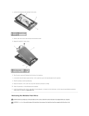
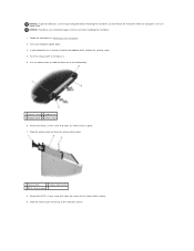
... on or in place. 9. If your computer before removing the hard drive. Remove the M2.5 x 5-mm screw that holds the release latch in to slide the drive out of the hard drive carrier. Do not remove the hard drive while the computer is on Your Computer. 2. NOTICE: Hard drives are extremely fragile. Use the release latch to release it...
... on or in place. 9. If your computer before removing the hard drive. Remove the M2.5 x 5-mm screw that holds the release latch in to slide the drive out of the hard drive carrier. Do not remove the hard drive while the computer is on Your Computer. 2. NOTICE: Hard drives are extremely fragile. Use the release latch to release it...
Service Manual
Page 57
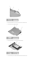
Lift the hard drive up at an angle and disconnect it from the hard drive bracket. 1 hard drive carrier 2 M2.5 x 5-mm screws (4) 3 hard drive 4 hard drive bracket 13. Remove the four M2.5 x 5 screws from the hard drive carrier. Lift the cover up at an angle and remove. 1 cover 2 M2.5 x 5-mm screws (3) 3 hard drive carrier 12. 1 M2.5 x 5-mm screw 2 release latch carrier 3 hard drive carrier 10. Remove the three M2.5 x 5-mm screws on the cover of the hard drive carrier. 11.
Lift the hard drive up at an angle and disconnect it from the hard drive bracket. 1 hard drive carrier 2 M2.5 x 5-mm screws (4) 3 hard drive 4 hard drive bracket 13. Remove the four M2.5 x 5 screws from the hard drive carrier. Lift the cover up at an angle and remove. 1 cover 2 M2.5 x 5-mm screws (3) 3 hard drive carrier 12. 1 M2.5 x 5-mm screw 2 release latch carrier 3 hard drive carrier 10. Remove the three M2.5 x 5-mm screws on the cover of the hard drive carrier. 11.
Service Manual
Page 58
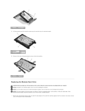
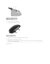
... fragile. With the top of the procedures in damage to slide the hard drive into place. 1 hard drive 2 hard drive carrier 14. NOTICE: Use firm and even pressure to the connector. The...hard drive. 1 hard drive 2 blue bumper Replacing the Modular Hard Drive CAUTION: Before you begin any of the bumper facing up . 1. Lift the connector-end of the hard drive and remove the hard drive from the connector, then enclose the two sides of the hard drive opposite from the hard drive bracket. 1 hard drive 2 connector 3 hard drive bracket 15. Pull out on the end of the hard drive...
... fragile. With the top of the procedures in damage to slide the hard drive into place. 1 hard drive 2 hard drive carrier 14. NOTICE: Use firm and even pressure to the connector. The...hard drive. 1 hard drive 2 blue bumper Replacing the Modular Hard Drive CAUTION: Before you begin any of the bumper facing up . 1. Lift the connector-end of the hard drive and remove the hard drive from the connector, then enclose the two sides of the hard drive opposite from the hard drive bracket. 1 hard drive 2 connector 3 hard drive bracket 15. Pull out on the end of the hard drive...
Service Manual
Page 59
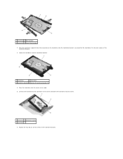
.... 1 hard drive 2 hard drive carrier 3 connector 6. Replace the four M2.5 x 5-mm screws in the carrier and lower the hard drive into the carrier at an angle. 5. Lower the hard drive into each corner of the hard drive bracket. 3. Place the end that is opposite from the connector on the hard drive into the hard drive bracket, ensuring that the hard drive fits into the hard drive bracket. 1 hard drive 2 connector 3 hard drive...
.... 1 hard drive 2 hard drive carrier 3 connector 6. Replace the four M2.5 x 5-mm screws in the carrier and lower the hard drive into the carrier at an angle. 5. Lower the hard drive into each corner of the hard drive bracket. 3. Place the end that is opposite from the connector on the hard drive into the hard drive bracket, ensuring that the hard drive fits into the hard drive bracket. 1 hard drive 2 connector 3 hard drive...
Service Manual
Page 60
... and replace the three M2.5 x 5-mm screws. 1 notches in place. 1 M2.5 x 5-mm screw 2 release latch carrier 3 hard drive carrier 11. Attach the side of the cover where it is angled, ensuring the tabs on the cover fit properly into the notches on ...carrier cover 3 M2.5 x 5-mm screws (3) 9. Slide the release latch carrier into the hard drive carrier. 12. Replace the M2.5 x 5-mm screw that holds the carrier for the release latch in hard drive carrier 2 tabs on the carrier. 8. 1 hard drive carrier 2 M2.5 x 5-mm screws (4) 3 hard drive 4 hard drive bracket 7.
... and replace the three M2.5 x 5-mm screws. 1 notches in place. 1 M2.5 x 5-mm screw 2 release latch carrier 3 hard drive carrier 11. Attach the side of the cover where it is angled, ensuring the tabs on the cover fit properly into the notches on ...carrier cover 3 M2.5 x 5-mm screws (3) 9. Slide the release latch carrier into the hard drive carrier. 12. Replace the M2.5 x 5-mm screw that holds the carrier for the release latch in hard drive carrier 2 tabs on the carrier. 8. 1 hard drive carrier 2 M2.5 x 5-mm screws (4) 3 hard drive 4 hard drive bracket 7.
Service Manual
Page 61
... latch in to Contents Page Follow the procedures in place. 1 hard drive carrier 2 release latch 15. Slide the hard drive carrier into the modular bay. 14. If your computer has a security screw for your computer at support.dell.com. Back to hold the carrier in After Working on Your ...Computer. 17. For more information, see the Setup and Quick Reference Guide that shipped with your computer, as needed. 1 release latch 2 hard drive carrier 3 M2.5 x 5-mm screw 13...
... latch in to Contents Page Follow the procedures in place. 1 hard drive carrier 2 release latch 15. Slide the hard drive carrier into the modular bay. 14. If your computer has a security screw for your computer at support.dell.com. Back to hold the carrier in After Working on Your ...Computer. 17. For more information, see the Setup and Quick Reference Guide that shipped with your computer, as needed. 1 release latch 2 hard drive carrier 3 M2.5 x 5-mm screw 13...
Service Manual
Page 71
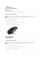
... Working on Your Computer. 2. Back to Contents Page Modular Drive Dell™ Latitude™ E6400 and E6400 ATG and Mobile Workstation Precision™ M2400 Service Manual Removing the Modular Drive Replacing the Modular Drive The modular drive supports either a second hard drive, an optical drive, or a an air bay for the modular drive, remove the security screw. 4. Back to Contents Page NOTE...
... Working on Your Computer. 2. Back to Contents Page Modular Drive Dell™ Latitude™ E6400 and E6400 ATG and Mobile Workstation Precision™ M2400 Service Manual Removing the Modular Drive Replacing the Modular Drive The modular drive supports either a second hard drive, an optical drive, or a an air bay for the modular drive, remove the security screw. 4. Back to Contents Page NOTE...


