
Owners Manual
Page 6
16 System Board 65 Removing the System Board 65 Replacing the System Board 66 Entering the Service Tag in the BIOS 67 17 Feet 69 Removing the Feet 69 Replacing the Feet 70 18 Middle Frame 71 Removing the Middle Frame 71 Replacing the Middle Frame 72 19 Processor Heat-Sink Fan 75 Removing the Processor Heat-Sink Fan 75 Replacing the Processor Heat-Sink Fan 76 20 Processor Heat-Sink 79 Removing the Processor Heat-Sink 79 Replacing the Processor Heat-Sink 80 6 Contents
16 System Board 65 Removing the System Board 65 Replacing the System Board 66 Entering the Service Tag in the BIOS 67 17 Feet 69 Removing the Feet 69 Replacing the Feet 70 18 Middle Frame 71 Removing the Middle Frame 71 Replacing the Middle Frame 72 19 Processor Heat-Sink Fan 75 Removing the Processor Heat-Sink Fan 75 Replacing the Processor Heat-Sink Fan 76 20 Processor Heat-Sink 79 Removing the Processor Heat-Sink 79 Replacing the Processor Heat-Sink 80 6 Contents
Owners Manual
Page 7
21 Processor 83 Removing the Processor 83 Replacing the Processor 84 22 Antenna-In Connector 89 Removing the Antenna-In Connector 89 Replacing the Antenna-In Connector 90 23 Antenna Module 93 Removing the Antenna Module 93 Replacing the Antenna Module 94 24 Power-Button Board 97 Removing the Power-Button Board 97 Replacing the Antenna-In Connector 98 25 Speakers 101 Removing the Speakers 101 Replacing the Speakers 102 26 Touch-Screen Control Board (Optional) 105 Removing the Touch-Screen Control Board 105 Contents 7
21 Processor 83 Removing the Processor 83 Replacing the Processor 84 22 Antenna-In Connector 89 Removing the Antenna-In Connector 89 Replacing the Antenna-In Connector 90 23 Antenna Module 93 Removing the Antenna Module 93 Replacing the Antenna Module 94 24 Power-Button Board 97 Removing the Power-Button Board 97 Replacing the Antenna-In Connector 98 25 Speakers 101 Removing the Speakers 101 Replacing the Speakers 102 26 Touch-Screen Control Board (Optional) 105 Removing the Touch-Screen Control Board 105 Contents 7
Owners Manual
Page 16
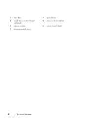
1 hard drive 3 touch-screen control board (optional) 5 camera module 7 memory-module cover 2 optical drive 4 processor heat-sink fan 6 system-board shield 16 Technical Overview
1 hard drive 3 touch-screen control board (optional) 5 camera module 7 memory-module cover 2 optical drive 4 processor heat-sink fan 6 system-board shield 16 Technical Overview
Owners Manual
Page 18
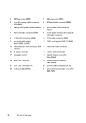
... CMOS reset jumper (CMOS_CLEAR) 13 infrared blaster cable connector (CIR 14 system-fan cable connector Emitter) 15 IR-cable connector 16 camera-cable connector 17 processor socket 18 memory-module connector (CHA-DIMM) 19 Mini-Card connector 20 memory-module connector (CHB-DIMM) 21 Mini-Card connector (TV) 22 speaker-cable...
... CMOS reset jumper (CMOS_CLEAR) 13 infrared blaster cable connector (CIR 14 system-fan cable connector Emitter) 15 IR-cable connector 16 camera-cable connector 17 processor socket 18 memory-module connector (CHA-DIMM) 19 Mini-Card connector 20 memory-module connector (CHB-DIMM) 21 Mini-Card connector (TV) 22 speaker-cable...
Owners Manual
Page 65
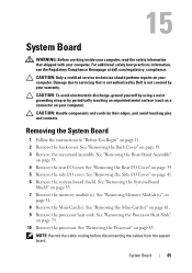
... page 19. 3 Remove the rear-stand assembly. System Board 65 See "Removing the Processor Heat-Sink" on page 41. 6 Remove the system-board shield. For additional safety best practices information, see the Regulatory Compliance Homepage at dell.com/regulatory_compliance. NOTE: Record the cable routing before disconnecting the cables from the system board...
... page 19. 3 Remove the rear-stand assembly. System Board 65 See "Removing the Processor Heat-Sink" on page 41. 6 Remove the system-board shield. For additional safety best practices information, see the Regulatory Compliance Homepage at dell.com/regulatory_compliance. NOTE: Record the cable routing before disconnecting the cables from the system board...
Owners Manual
Page 66
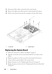
... Remove the eight screws that secure the system board to the chassis. 4 Connect all the required cables to the system board. 5 Replace the processor. See "Replacing the Processor Heat-Sink" on the chassis. 3 Replace the eight screws that secure the system board to the chassis. 13 Lift the system board away from... Begin" on page 11. 2 Align the screw holes on the system board with the screw holes on page 80. 66 System Board See "Replacing the Processor" on page 84. 6 Replace the...
... Remove the eight screws that secure the system board to the chassis. 4 Connect all the required cables to the system board. 5 Replace the processor. See "Replacing the Processor Heat-Sink" on the chassis. 3 Replace the eight screws that secure the system board to the chassis. 13 Lift the system board away from... Begin" on page 11. 2 Align the screw holes on the system board with the screw holes on page 80. 66 System Board See "Replacing the Processor" on page 84. 6 Replace the...
Owners Manual
Page 75
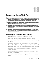
...VESA Mount" on page 37. 5 Remove the rear I /O Cover" on page 41. 7 Remove the system-board shield. Ensure that secure the processor heat-sink fan to cool before you touch it has had sufficient time to the chassis. CAUTION: Only a certified service technician should perform repairs on... in "Before You Begin" on page 19. 3 Remove the rear-stand assembly. 18 Processor Heat-Sink Fan WARNING: Before working inside your computer, read the safety information that is not authorized by Dell is not covered by periodically touching an unpainted metal surface (such as a connector on your...
...VESA Mount" on page 37. 5 Remove the rear I /O Cover" on page 41. 7 Remove the system-board shield. Ensure that secure the processor heat-sink fan to cool before you touch it has had sufficient time to the chassis. CAUTION: Only a certified service technician should perform repairs on... in "Before You Begin" on page 19. 3 Remove the rear-stand assembly. 18 Processor Heat-Sink Fan WARNING: Before working inside your computer, read the safety information that is not authorized by Dell is not covered by periodically touching an unpainted metal surface (such as a connector on your...

Owners Manual
Page 76
... in "Before You Begin" on page 11. 2 Align the screw holes on the processor heat-sink fan with its cable away from the chassis. 10 Carefully peel the silver foil from the processor heat-sink. 11 Lift the processor heat-sink fan along with the screw holes on the chassis. 3 Adhere the silver... foil on the processor heat-sink. 4 Replace the three screws that secure the processor heat-sink fan to the chassis. 5 Connect the processor heat-sink fan cable to the connector (CPU FAN) on the system board. 76 Heat-Sink Fans...
... in "Before You Begin" on page 11. 2 Align the screw holes on the processor heat-sink fan with its cable away from the chassis. 10 Carefully peel the silver foil from the processor heat-sink. 11 Lift the processor heat-sink fan along with the screw holes on the chassis. 3 Adhere the silver... foil on the processor heat-sink. 4 Replace the three screws that secure the processor heat-sink fan to the chassis. 5 Connect the processor heat-sink fan cable to the connector (CPU FAN) on the system board. 76 Heat-Sink Fans...

Owners Manual
Page 79
..., see the Regulatory Compliance Homepage at dell.com/regulatory_compliance. CAUTION: To avoid electrostatic discharge, ground yourself by using a wrist grounding strap or by your warranty. Removing the Processor Heat-Sink CAUTION: To ensure maximum cooling for the processor, do not touch the heat transfer...touch it. See "Removing the Rear-Stand Assembly" on your computer. 19 Processor Heat-Sink WARNING: Before working inside your computer, read the safety information that is not authorized by Dell is not covered by periodically touching an unpainted metal surface (such as a ...
..., see the Regulatory Compliance Homepage at dell.com/regulatory_compliance. CAUTION: To avoid electrostatic discharge, ground yourself by using a wrist grounding strap or by your warranty. Removing the Processor Heat-Sink CAUTION: To ensure maximum cooling for the processor, do not touch the heat transfer...touch it. See "Removing the Rear-Stand Assembly" on your computer. 19 Processor Heat-Sink WARNING: Before working inside your computer, read the safety information that is not authorized by Dell is not covered by periodically touching an unpainted metal surface (such as a ...

Owners Manual
Page 80
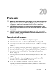
... in "Before You Begin" on your computer model. 1 2 3 1 screw 3 captive screws (4) 2 processor heat-sink Replacing the Processor Heat-Sink CAUTION: Incorrect alignment of the processor heat-sink can be reused if the original processor and processor heat-sink are reinstalled together. NOTE: The appearance of the processor heat-sink may vary based on page 11. 80...
... in "Before You Begin" on your computer model. 1 2 3 1 screw 3 captive screws (4) 2 processor heat-sink Replacing the Processor Heat-Sink CAUTION: Incorrect alignment of the processor heat-sink can be reused if the original processor and processor heat-sink are reinstalled together. NOTE: The appearance of the processor heat-sink may vary based on page 11. 80...

Owners Manual
Page 81
...reapply it. 3 Replace the screw that no stray screws remain inside the computer. See "Replacing the Back Cover" on page 40. 7 Replace the side I /O cover. Processor Heat Sink 81 CAUTION: Before turning on the computer, replace all attached devices to the chassis. 4 Align the four captive screws on the... processor heat-sink with the screw holes on page 54. 6 Replace the rear I /O cover. See "Replacing the System-Board Shield" on the system board and ...
...reapply it. 3 Replace the screw that no stray screws remain inside the computer. See "Replacing the Back Cover" on page 40. 7 Replace the side I /O cover. Processor Heat Sink 81 CAUTION: Before turning on the computer, replace all attached devices to the chassis. 4 Align the four captive screws on the... processor heat-sink with the screw holes on page 54. 6 Replace the rear I /O cover. See "Replacing the System-Board Shield" on the system board and ...
Owners Manual
Page 83
... with your warranty. Damage due to servicing that is not authorized by Dell is ready for the new processor. See "Removing the Back Cover" on page 11. 2 Remove the back cover. Processor 83 Removing the Processor 1 Follow the instructions in the release position so that secures it.... system-board shield. See "Removing the System-Board Shield" on page 53. 7 Remove the processor heat-sink. For additional safety best practices information, see the Regulatory Compliance Homepage at dell.com/regulatory_compliance. Leave the release lever extended in "Before You Begin" on page 19. 3 Remove...
... with your warranty. Damage due to servicing that is not authorized by Dell is ready for the new processor. See "Removing the Back Cover" on page 11. 2 Remove the back cover. Processor 83 Removing the Processor 1 Follow the instructions in the release position so that secures it.... system-board shield. See "Removing the System-Board Shield" on page 53. 7 Remove the processor heat-sink. For additional safety best practices information, see the Regulatory Compliance Homepage at dell.com/regulatory_compliance. Leave the release lever extended in "Before You Begin" on page 19. 3 Remove...

Owners Manual
Page 84
1 2 3 1 processor cover 3 release lever 2 tab 10 Gently lift the processor to remove it from the socket. 2 1 1 socket 2 processor Replacing the Processor 1 Follow the instructions in "Before You Begin" on page 11. 2 Unpack the new processor, being careful not to touch the underside of the processor. CAUTION: Ground yourself by touching an unpainted metal surface or the computer stand. 84 Processor
1 2 3 1 processor cover 3 release lever 2 tab 10 Gently lift the processor to remove it from the socket. 2 1 1 socket 2 processor Replacing the Processor 1 Follow the instructions in "Before You Begin" on page 11. 2 Unpack the new processor, being careful not to touch the underside of the processor. CAUTION: Ground yourself by touching an unpainted metal surface or the computer stand. 84 Processor

Owners Manual
Page 85
... on the socket. 5 Align the pin-1 corners of the processor and socket. 4 5 3 2 1 1 socket 3 alignment tabs (2) 5 processor pin-1 indicator 2 processor 4 alignment notches (2) CAUTION: Ensure that the processor cover notch is positioned underneath the alignment post. 6 When the processor is fully seated in the socket, close the processor cover. 7 Pivot the release lever down and place it under...
... on the socket. 5 Align the pin-1 corners of the processor and socket. 4 5 3 2 1 1 socket 3 alignment tabs (2) 5 processor pin-1 indicator 2 processor 4 alignment notches (2) CAUTION: Ensure that the processor cover notch is positioned underneath the alignment post. 6 When the processor is fully seated in the socket, close the processor cover. 7 Pivot the release lever down and place it under...

Owners Manual
Page 86
...11 Replace the system-board shield. CAUTION: Ensure that you apply new thermal grease. 4 5 6 3 1 2 1 alignment post 3 processor cover 5 processor 2 tab 4 release lever 6 processor cover notch 8 Clean the thermal grease from the bottom of the heat sink. 9 Apply the new thermal grease to the... processor. New thermal grease is critical for optimal processor operation. See "Replacing the Processor Heat-Sink" on page 54. 86 Processor CAUTION: You must position the processor correctly in the processor socket to avoid permanent damage to the top...
...11 Replace the system-board shield. CAUTION: Ensure that you apply new thermal grease. 4 5 6 3 1 2 1 alignment post 3 processor cover 5 processor 2 tab 4 release lever 6 processor cover notch 8 Clean the thermal grease from the bottom of the heat sink. 9 Apply the new thermal grease to the... processor. New thermal grease is critical for optimal processor operation. See "Replacing the Processor Heat-Sink" on page 54. 86 Processor CAUTION: You must position the processor correctly in the processor socket to avoid permanent damage to the top...

Owners Manual
Page 87
Processor 87 CAUTION: Before turning on page 36. 15 Replace the back cover. See "Replacing the Rear-Stand Assembly" on the computer, replace all attached devices ...
Processor 87 CAUTION: Before turning on page 36. 15 Replace the back cover. See "Replacing the Rear-Stand Assembly" on the computer, replace all attached devices ...
Owners Manual
Page 93
...System-Board Shield" on page 19. 3 Remove the rear-stand assembly. For additional safety best practices information, see the Regulatory Compliance Homepage at dell.com/regulatory_compliance. See "Removing the Rear-Stand Assembly" on your warranty. See "Removing the Middle Frame" on page 71. 10 Follow instructions ...in step 8 to step 11 in "Removing the Processor Heat-Sink Fan" on page 75. 11 Disconnect the antenna cables from step 3 to servicing that is not authorized by Dell is not covered by periodically touching an unpainted metal surface (such as a ...
...System-Board Shield" on page 19. 3 Remove the rear-stand assembly. For additional safety best practices information, see the Regulatory Compliance Homepage at dell.com/regulatory_compliance. See "Removing the Rear-Stand Assembly" on your warranty. See "Removing the Middle Frame" on page 71. 10 Follow instructions ...in step 8 to step 11 in "Removing the Processor Heat-Sink Fan" on page 75. 11 Disconnect the antenna cables from step 3 to servicing that is not authorized by Dell is not covered by periodically touching an unpainted metal surface (such as a ...

Owners Manual
Page 94
... guides on the chassis. 5 Connect the antenna cables to the connectors on the Mini-card. 6 Follow the instructions from step 2 to step 5 in "Replacing the Processor Heat-Sink Fan" on page 76. 7 Replace the middle frame.
... guides on the chassis. 5 Connect the antenna cables to the connectors on the Mini-card. 6 Follow the instructions from step 2 to step 5 in "Replacing the Processor Heat-Sink Fan" on page 76. 7 Replace the middle frame.
Owners Manual
Page 109
... For additional safety best practices information, see the Regulatory Compliance Homepage at dell.com/regulatory_compliance. See "Removing the Audio Video (AV) Board" on page 39. 8 Remove the side I /O Cover" on page 43. 11 Remove the processor heat-sink fan. See "Removing the System-Board Shield" on page ...11. 2 Remove the back cover. 26 Display WARNING: Before working inside your computer, read the safety information that is not authorized by Dell is not covered by periodically touching...
... For additional safety best practices information, see the Regulatory Compliance Homepage at dell.com/regulatory_compliance. See "Removing the Audio Video (AV) Board" on page 39. 8 Remove the side I /O Cover" on page 43. 11 Remove the processor heat-sink fan. See "Removing the System-Board Shield" on page ...11. 2 Remove the back cover. 26 Display WARNING: Before working inside your computer, read the safety information that is not authorized by Dell is not covered by periodically touching...
Owners Manual
Page 112
... rear-stand assembly. See "Replacing the VESA Mount" on page 45. 12 Replace the system-board shield. See "Replacing the Processor Heat-Sink Fan" on page 72. 10 Replace the processor heat-sink fan. See "Replacing the Middle Frame" on page 76. 11 Replace the AV board. Failure to do so may...
... rear-stand assembly. See "Replacing the VESA Mount" on page 45. 12 Replace the system-board shield. See "Replacing the Processor Heat-Sink Fan" on page 72. 10 Replace the processor heat-sink fan. See "Replacing the Middle Frame" on page 76. 11 Replace the AV board. Failure to do so may...


