
Quick Start Guide (PDF)
Page 1
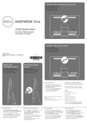
...Reforma 2620 - Meer informatie • Klik op Start→ Alle programa's→ Dell Helpdocumentatie of the Official Mexican Standard (NOM): Importer: Dell México S.A. Dell™, the DELL logo, and Inspiron™ are trademarks of problemen voor de klantenservice. Lomas Altas 11950 México,...teclado e o mouse One 2320 Quick Start Snel starten | Démarrage rapide Inicio rápido | Início rápido Uniquely Dell support.dell.com/manuals | www.dell.com 2011 - 07 Printed in China 0GX7TPA00 Adjust the computer stand Pas de stand van de computer aan ...
...Reforma 2620 - Meer informatie • Klik op Start→ Alle programa's→ Dell Helpdocumentatie of the Official Mexican Standard (NOM): Importer: Dell México S.A. Dell™, the DELL logo, and Inspiron™ are trademarks of problemen voor de klantenservice. Lomas Altas 11950 México,...teclado e o mouse One 2320 Quick Start Snel starten | Démarrage rapide Inicio rápido | Início rápido Uniquely Dell support.dell.com/manuals | www.dell.com 2011 - 07 Printed in China 0GX7TPA00 Adjust the computer stand Pas de stand van de computer aan ...
Owners Manual
Page 4
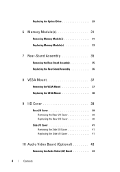
Replacing the Optical Drive 29 6 Memory Module(s 31 Removing Memory Module(s 31 Replacing Memory Module(s 33 7 Rear-Stand Assembly 35 Removing the Rear-Stand Assembly 35 Replacing the Rear-Stand Assembly 36 8 VESA Mount 37 Removing the VESA Mount 37 Replacing the VESA Mount 38 9 I/O Cover 39 Rear I/O Cover 39 Removing the Rear I/O Cover 39 Replacing the Rear I/O Cover 40 Side I/O Cover 41 Removing the Side I/O Cover 41 Replacing the Side I/O Cover 41 10 Audio Video Board (Optional 43 Removing the Audio Video (AV) Board 43 4 Contents
Replacing the Optical Drive 29 6 Memory Module(s 31 Removing Memory Module(s 31 Replacing Memory Module(s 33 7 Rear-Stand Assembly 35 Removing the Rear-Stand Assembly 35 Replacing the Rear-Stand Assembly 36 8 VESA Mount 37 Removing the VESA Mount 37 Replacing the VESA Mount 38 9 I/O Cover 39 Rear I/O Cover 39 Removing the Rear I/O Cover 39 Replacing the Rear I/O Cover 40 Side I/O Cover 41 Removing the Side I/O Cover 41 Replacing the Side I/O Cover 41 10 Audio Video Board (Optional 43 Removing the Audio Video (AV) Board 43 4 Contents
Owners Manual
Page 35
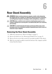
...the chassis. 4 Slide the rear-stand assembly towards the bottom of the computer and lift it away from the chassis. Rear Stand Cover 35 For additional safety best practices information, see the Regulatory Compliance Homepage at dell.com/regulatory_compliance. CAUTION: To avoid ...electrostatic discharge, ground yourself by using a wrist grounding strap or by your computer. Removing the Rear-Stand Assembly 1 Follow the instructions in "Before You Begin" on...
...the chassis. 4 Slide the rear-stand assembly towards the bottom of the computer and lift it away from the chassis. Rear Stand Cover 35 For additional safety best practices information, see the Regulatory Compliance Homepage at dell.com/regulatory_compliance. CAUTION: To avoid ...electrostatic discharge, ground yourself by using a wrist grounding strap or by your computer. Removing the Rear-Stand Assembly 1 Follow the instructions in "Before You Begin" on...
Owners Manual
Page 36
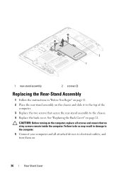
... 1 Follow the instructions in damage to the computer. 5 Connect your computer and all screws and ensure that secure the rear-stand assembly to the chassis. 4 Replace the back cover. See "Replacing the Back Cover" on the computer, replace all attached devices to the top of the ... screws that no stray screws remain inside the computer. Failure to do so may result in "Before You Begin" on page 11. 2 Place the rear-stand assembly on the chassis and slide it to electrical outlets, and turn them on. 36 Rear...
... 1 Follow the instructions in damage to the computer. 5 Connect your computer and all screws and ensure that secure the rear-stand assembly to the chassis. 4 Replace the back cover. See "Replacing the Back Cover" on the computer, replace all attached devices to the top of the ... screws that no stray screws remain inside the computer. Failure to do so may result in "Before You Begin" on page 11. 2 Place the rear-stand assembly on the chassis and slide it to electrical outlets, and turn them on. 36 Rear...
Owners Manual
Page 37
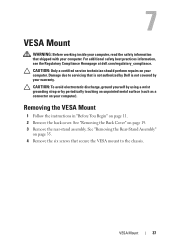
See "Removing the Rear-Stand Assembly" on page 35. 4 Remove the six screws that secure the VESA mount to servicing that shipped with your computer). VESA Mount 37 CAUTION: To ... 11. 2 Remove the back cover. See "Removing the Back Cover" on your computer. For additional safety best practices information, see the Regulatory Compliance Homepage at dell.com/regulatory_compliance. 7 VESA Mount WARNING: Before working inside your computer, read the safety information that is not authorized by...
See "Removing the Rear-Stand Assembly" on page 35. 4 Remove the six screws that secure the VESA mount to servicing that shipped with your computer). VESA Mount 37 CAUTION: To ... 11. 2 Remove the back cover. See "Removing the Back Cover" on your computer. For additional safety best practices information, see the Regulatory Compliance Homepage at dell.com/regulatory_compliance. 7 VESA Mount WARNING: Before working inside your computer, read the safety information that is not authorized by...
Owners Manual
Page 38
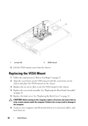
..." on the computer, replace all attached devices to the chassis. 4 Replace the rear-stand assembly. CAUTION: Before turning on page 36. 5 Replace the back cover. Failure to do so may result in "Before You Begin" on page 11. 2 Align ...
..." on the computer, replace all attached devices to the chassis. 4 Replace the rear-stand assembly. CAUTION: Before turning on page 36. 5 Replace the back cover. Failure to do so may result in "Before You Begin" on page 11. 2 Align ...
Owners Manual
Page 39
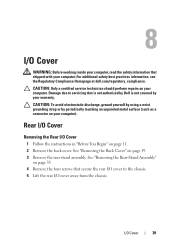
... screws that secure the rear I /O Cover WARNING: Before working inside your computer, read the safety information that is not authorized by Dell is not covered by periodically touching an unpainted metal surface (such as a connector on your computer. Damage due to the chassis. 5...away from the chassis. For additional safety best practices information, see the Regulatory Compliance Homepage at dell.com/regulatory_compliance. Rear I/O Cover Removing the Rear I /O Cover 39 See "Removing the Rear-Stand Assembly" on page 11. 2 Remove the back cover. CAUTION: Only a certified service ...
... screws that secure the rear I /O Cover WARNING: Before working inside your computer, read the safety information that is not authorized by Dell is not covered by periodically touching an unpainted metal surface (such as a connector on your computer. Damage due to the chassis. 5...away from the chassis. For additional safety best practices information, see the Regulatory Compliance Homepage at dell.com/regulatory_compliance. Rear I/O Cover Removing the Rear I /O Cover 39 See "Removing the Rear-Stand Assembly" on page 11. 2 Remove the back cover. CAUTION: Only a certified service ...
Owners Manual
Page 40
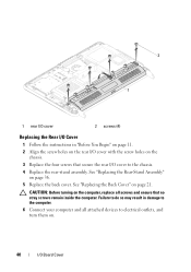
See "Replacing the Rear-Stand Assembly" on page 21. CAUTION: Before turning on the computer, replace all attached devices to electrical outlets, and turn them on the chassis. 3 Replace the ... instructions in damage to the computer. 6 Connect your computer and all screws and ensure that secure the rear I/O cover to the chassis. 4 Replace the rear-stand assembly. See "Replacing the Back Cover" on page 36. 5 Replace the back cover.
See "Replacing the Rear-Stand Assembly" on page 21. CAUTION: Before turning on the computer, replace all attached devices to electrical outlets, and turn them on the chassis. 3 Replace the ... instructions in damage to the computer. 6 Connect your computer and all screws and ensure that secure the rear I/O cover to the chassis. 4 Replace the rear-stand assembly. See "Replacing the Back Cover" on page 36. 5 Replace the back cover.
Owners Manual
Page 43
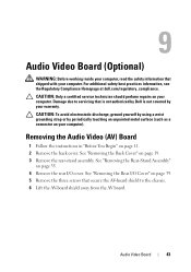
... strap or by your warranty. See "Removing the Rear I /O cover. For additional safety best practices information, see the Regulatory Compliance Homepage at dell.com/regulatory_compliance. Removing the Audio Video (AV) Board 1 Follow the instructions in "Before You Begin" on your computer. See "Removing the Rear...-Stand Assembly" on page 35. 4 Remove the rear I /O Cover" on page 39. 5 Remove the three screws that secure the AV-board shield ...
... strap or by your warranty. See "Removing the Rear I /O cover. For additional safety best practices information, see the Regulatory Compliance Homepage at dell.com/regulatory_compliance. Removing the Audio Video (AV) Board 1 Follow the instructions in "Before You Begin" on your computer. See "Removing the Rear...-Stand Assembly" on page 35. 4 Remove the rear I /O Cover" on page 39. 5 Remove the three screws that secure the AV-board shield ...
Owners Manual
Page 45
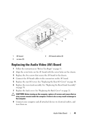
See "Replacing the Rear-Stand Assembly" on . Failure to do so may result in "Before You Begin" on page 11. 2 Align the screw holes on the AV board with the ... screws and ensure that secure the AV board to the chassis. 4 Connect the AV-board cables to the connectors on page 40. 6 Replace the rear-stand assembly. See "Replacing the Rear I/O Cover" on the AV board. 5 Replace the rear I/O cover.
See "Replacing the Rear-Stand Assembly" on . Failure to do so may result in "Before You Begin" on page 11. 2 Align the screw holes on the AV board with the ... screws and ensure that secure the AV board to the chassis. 4 Connect the AV-board cables to the connectors on page 40. 6 Replace the rear-stand assembly. See "Replacing the Rear I/O Cover" on the AV board. 5 Replace the rear I/O cover.
Owners Manual
Page 47
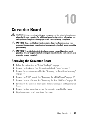
...Removing the Rear I /O cover. For additional safety best practices information, see the Regulatory Compliance Homepage at dell.com/regulatory_compliance. Main Chassis 47 See "Removing the Rear-Stand Assembly" on the converter board. 7 Remove the two screws that secure the converter board to servicing ...that is not authorized by Dell is not covered by periodically touching an unpainted metal surface (such as ...
...Removing the Rear I /O cover. For additional safety best practices information, see the Regulatory Compliance Homepage at dell.com/regulatory_compliance. Main Chassis 47 See "Removing the Rear-Stand Assembly" on the converter board. 7 Remove the two screws that secure the converter board to servicing ...that is not authorized by Dell is not covered by periodically touching an unpainted metal surface (such as ...
Owners Manual
Page 48
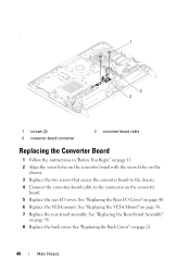
See "Replacing the Rear-Stand Assembly" on page 21. 48 Main Chassis See "Replacing the Rear I /O cover. . 1 2 3 1 screws (2) 3 converter-board connector 2 converter-board cable Replacing the Converter Board 1 Follow the ... VESA mount. See "Replacing the Back Cover" on page 36. 8 Replace the back cover. See "Replacing the VESA Mount" on page 38. 7 Replace the rear-stand assembly.
See "Replacing the Rear-Stand Assembly" on page 21. 48 Main Chassis See "Replacing the Rear I /O cover. . 1 2 3 1 screws (2) 3 converter-board connector 2 converter-board cable Replacing the Converter Board 1 Follow the ... VESA mount. See "Replacing the Back Cover" on page 36. 8 Replace the back cover. See "Replacing the VESA Mount" on page 38. 7 Replace the rear-stand assembly.
Owners Manual
Page 51
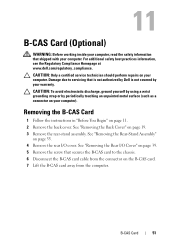
11 B-CAS Card (Optional) WARNING: Before working inside your computer, read the safety information that is not authorized by Dell is not covered by periodically touching an unpainted metal surface (such as a connector on your computer). Damage due to the chassis. 6 Disconnect... servicing that shipped with your computer. Removing the B-CAS Card 1 Follow the instructions in "Before You Begin" on page 19. 3 Remove the rear-stand assembly. CAUTION: Only a certified service technician should perform repairs on the B-CAS card. 7 Lift the B-CAS card away from the connector on your ...
11 B-CAS Card (Optional) WARNING: Before working inside your computer, read the safety information that is not authorized by Dell is not covered by periodically touching an unpainted metal surface (such as a connector on your computer). Damage due to the chassis. 6 Disconnect... servicing that shipped with your computer. Removing the B-CAS Card 1 Follow the instructions in "Before You Begin" on page 19. 3 Remove the rear-stand assembly. CAUTION: Only a certified service technician should perform repairs on the B-CAS card. 7 Lift the B-CAS card away from the connector on your ...
Owners Manual
Page 52
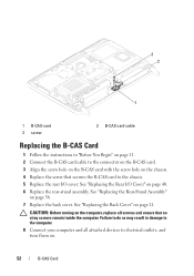
... computer and all screws and ensure that secures the B-CAS card to the chassis. 5 Replace the rear I /O Cover" on page 40. 6 Replace the rear-stand assembly. See "Replacing the Back Cover" on page 36. 7 Replace the back cover. Failure to do so may result in "Before You Begin" on page... cable to electrical outlets, and turn them on the chassis. 4 Replace the screw that no stray screws remain inside the computer. See "Replacing the Rear-Stand Assembly" on page 21. CAUTION: Before turning on the computer, replace all attached devices to the connector on the B-CAS card. 3 Align the screw...
... computer and all screws and ensure that secures the B-CAS card to the chassis. 5 Replace the rear I /O Cover" on page 40. 6 Replace the rear-stand assembly. See "Replacing the Back Cover" on page 36. 7 Replace the back cover. Failure to do so may result in "Before You Begin" on page... cable to electrical outlets, and turn them on the chassis. 4 Replace the screw that no stray screws remain inside the computer. See "Replacing the Rear-Stand Assembly" on page 21. CAUTION: Before turning on the computer, replace all attached devices to the connector on the B-CAS card. 3 Align the screw...
Owners Manual
Page 53
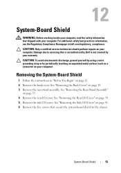
... computer). 12 System-Board Shield WARNING: Before working inside your computer, read the safety information that is not authorized by Dell is not covered by periodically touching an unpainted metal surface (such as a connector on your computer. For additional safety best... practices information, see the Regulatory Compliance Homepage at dell.com/regulatory_compliance. Removing the System-Board Shield 1 Follow the instructions in "Before You Begin" on page 19. 3 Remove the rear-stand assembly. See "Removing the Rear I/O Cover" on page 39. 5 Remove...
... computer). 12 System-Board Shield WARNING: Before working inside your computer, read the safety information that is not authorized by Dell is not covered by periodically touching an unpainted metal surface (such as a connector on your computer. For additional safety best... practices information, see the Regulatory Compliance Homepage at dell.com/regulatory_compliance. Removing the System-Board Shield 1 Follow the instructions in "Before You Begin" on page 19. 3 Remove the rear-stand assembly. See "Removing the Rear I/O Cover" on page 39. 5 Remove...
Owners Manual
Page 55
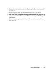
CAUTION: Before turning on . Failure to do so may result in damage to the computer. 8 Connect your computer and all attached devices to electrical outlets, and turn them on the computer, replace all screws and ensure that no stray screws remain inside the computer. See "Replacing the Back Cover" on page 36. 7 Replace the back cover. 6 Replace the rear-stand assembly. See "Replacing the Rear-Stand Assembly" on page 21. System-Board Shield 55
CAUTION: Before turning on . Failure to do so may result in damage to the computer. 8 Connect your computer and all attached devices to electrical outlets, and turn them on the computer, replace all screws and ensure that no stray screws remain inside the computer. See "Replacing the Back Cover" on page 36. 7 Replace the back cover. 6 Replace the rear-stand assembly. See "Replacing the Rear-Stand Assembly" on page 21. System-Board Shield 55
Owners Manual
Page 57
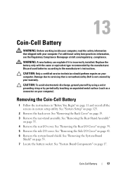
...system-board shield. Removing the Coin-Cell Battery 1 Follow the instructions in "Before You Begin" on page 19. 3 Remove the rear-stand assembly. See "Removing the Back Cover" on page 11 and record all the screens in system setup utility. See "Removing the System-...See "System Setup" on page 53. 7 Locate the battery socket. For additional safety best practices information, see the Regulatory Compliance Homepage at dell.com/regulatory_compliance. CAUTION: Only a certified service technician should perform repairs on your computer. See "Removing the Side I /O cover. 13 Coin...
...system-board shield. Removing the Coin-Cell Battery 1 Follow the instructions in "Before You Begin" on page 19. 3 Remove the rear-stand assembly. See "Removing the Back Cover" on page 11 and record all the screens in system setup utility. See "Removing the System-...See "System Setup" on page 53. 7 Locate the battery socket. For additional safety best practices information, see the Regulatory Compliance Homepage at dell.com/regulatory_compliance. CAUTION: Only a certified service technician should perform repairs on your computer. See "Removing the Side I /O cover. 13 Coin...
Owners Manual
Page 59
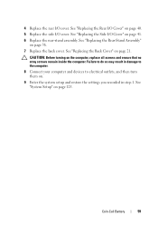
... settings you recorded in step 1. Coin-Cell Battery 59 See "Replacing the Side I/O Cover" on page 36. 7 Replace the back cover. See "Replacing the Rear-Stand Assembly" on page 41. 6 Replace the rear...
... settings you recorded in step 1. Coin-Cell Battery 59 See "Replacing the Side I/O Cover" on page 36. 7 Replace the back cover. See "Replacing the Rear-Stand Assembly" on page 41. 6 Replace the rear...
Owners Manual
Page 61
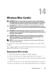
...(s) 1 Follow the instructions in "Before You Begin" on page 41. See "Removing the Side I /O cover. Wireless Mini-Card 61 NOTE: Dell does not guarantee compatibility or provide support for Wireless Local Area Network (WLAN) and a TV tuner module. If you ordered a wireless Mini-Card ...inside your computer, read the safety information that shipped with your computer). See "Removing the Rear-Stand Assembly" on your computer). Damage due to servicing that is not authorized by Dell is not covered by periodically touching an unpainted metal surface (such as a connector on your computer...
...(s) 1 Follow the instructions in "Before You Begin" on page 41. See "Removing the Side I /O cover. Wireless Mini-Card 61 NOTE: Dell does not guarantee compatibility or provide support for Wireless Local Area Network (WLAN) and a TV tuner module. If you ordered a wireless Mini-Card ...inside your computer, read the safety information that shipped with your computer). See "Removing the Rear-Stand Assembly" on your computer). Damage due to servicing that is not authorized by Dell is not covered by periodically touching an unpainted metal surface (such as a connector on your computer...
Owners Manual
Page 63
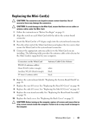
"Replacing the System-Board Shield" on page 36. 10 Replace the back cover. See "Replacing the Rear-Stand Assembly" on page 54. 7 Replace the rear I/O cover. Wireless Mini-Card 63 CAUTION: Before turning on the Mini-Card WLAN (2 antenna cables) Main WLAN (white ... Mini-Card(s) CAUTION: The connectors are installing. See "Replacing the Side I/O Cover" on page 40. 8 Replace the side I /O Cover" on page 41. 9 Replace the rear-stand assembly. CAUTION: To avoid damage to the computer. See "Replacing the Back Cover" on each Mini-Card with the tab in "Before You Begin" on...
"Replacing the System-Board Shield" on page 36. 10 Replace the back cover. See "Replacing the Rear-Stand Assembly" on page 54. 7 Replace the rear I/O cover. Wireless Mini-Card 63 CAUTION: Before turning on the Mini-Card WLAN (2 antenna cables) Main WLAN (white ... Mini-Card(s) CAUTION: The connectors are installing. See "Replacing the Side I/O Cover" on page 40. 8 Replace the side I /O Cover" on page 41. 9 Replace the rear-stand assembly. CAUTION: To avoid damage to the computer. See "Replacing the Back Cover" on each Mini-Card with the tab in "Before You Begin" on...


