
Owners Manual
Page 8
...-Screen Control Board. . . . . . 106 27 Display 109 Display Assembly 109 Removing the Display Assembly 109 Replacing the Display Assembly 111 Display Panel 113 Removing the Display Panel 113 Replacing the Display Panel 113 Display-Panel Brackets 114 Removing the Display-Panel Brackets 114 Replacing the Display-Panel Brackets 115 28 Camera Module 117 Removing the Camera Module 117 Replacing the Camera Module 118 29 Speaker Cover 121 Removing the Speaker Cover 121 Replacing the Speaker Cover 122 30 System Setup 125 Overview 125 Entering System Setup 125 System Setup Options...
...-Screen Control Board. . . . . . 106 27 Display 109 Display Assembly 109 Removing the Display Assembly 109 Replacing the Display Assembly 111 Display Panel 113 Removing the Display Panel 113 Replacing the Display Panel 113 Display-Panel Brackets 114 Removing the Display-Panel Brackets 114 Replacing the Display-Panel Brackets 115 28 Camera Module 117 Removing the Camera Module 117 Replacing the Camera Module 118 29 Speaker Cover 121 Removing the Speaker Cover 121 Replacing the Speaker Cover 122 30 System Setup 125 Overview 125 Entering System Setup 125 System Setup Options...
Owners Manual
Page 12
... at dell.com/regulatory_compliance. CAUTION: Only a certified service technician is unplugged to replace, remove, or install accessories. WARNING: Disconnect all power sources before opening the enclosure to ground the system board. 12 Before you begin working inside your computer and all fasteners installed before you disconnect the cable. See the safety instructions for complete information about safety precautions, working inside the computer. CAUTION: To disconnect a network cable...
... at dell.com/regulatory_compliance. CAUTION: Only a certified service technician is unplugged to replace, remove, or install accessories. WARNING: Disconnect all power sources before opening the enclosure to ground the system board. 12 Before you begin working inside your computer and all fasteners installed before you disconnect the cable. See the safety instructions for complete information about safety precautions, working inside the computer. CAUTION: To disconnect a network cable...
Owners Manual
Page 21
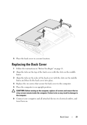
... the computer in damage to the computer. 6 Connect your computer and all attached devices to do so may result in an upright position. Failure to electrical outlets, and turn them on the computer, replace all screws and ensure that no stray screws remain inside the computer. Back Cover 21 CAUTION: Before turning on . 5 Place the back cover in a secure location.
... the computer in damage to the computer. 6 Connect your computer and all attached devices to do so may result in an upright position. Failure to electrical outlets, and turn them on the computer, replace all screws and ensure that no stray screws remain inside the computer. Back Cover 21 CAUTION: Before turning on . 5 Place the back cover in a secure location.
Owners Manual
Page 23
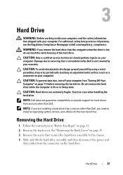
... not guarantee compatibility or provide support for hard drives from a source other than Dell, you need to install an operating system, drivers, and utilities on page 11. 2 Remove the back cover. NOTE: If you remove the hard drive from the connector on page 11) before removing the hard drive. 3 Hard Drive WARNING: Before working inside your computer, read the safety information that is not authorized by Dell is not covered by periodically touching an...
... not guarantee compatibility or provide support for hard drives from a source other than Dell, you need to install an operating system, drivers, and utilities on page 11. 2 Remove the back cover. NOTE: If you remove the hard drive from the connector on page 11) before removing the hard drive. 3 Hard Drive WARNING: Before working inside your computer, read the safety information that is not authorized by Dell is not covered by periodically touching an...
Owners Manual
Page 26
CAUTION: Before turning on . 26 Hard Drive Failure to do so may result in damage to the computer. 8 Connect your computer and all attached devices to electrical outlets, and turn them on the computer, replace all screws and ensure that no stray screws remain inside the computer.
CAUTION: Before turning on . 26 Hard Drive Failure to do so may result in damage to the computer. 8 Connect your computer and all attached devices to electrical outlets, and turn them on the computer, replace all screws and ensure that no stray screws remain inside the computer.
Owners Manual
Page 29
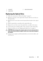
... remain inside the computer. CAUTION: Before turning on the computer, replace all attached devices to electrical outlets, and turn them on. 1 screws (2) 3 optical drive 2 optical-drive bracket Replacing the Optical Drive 1 Follow the instructions in damage to the computer. 8 Connect your computer and all screws and ensure that secures the optical-drive assembly to the chassis. 6 Connect the power and data cables to the connector on the optical drive. 7 Replace the back cover. Optical Drive 29...
... remain inside the computer. CAUTION: Before turning on the computer, replace all attached devices to electrical outlets, and turn them on. 1 screws (2) 3 optical drive 2 optical-drive bracket Replacing the Optical Drive 1 Follow the instructions in damage to the computer. 8 Connect your computer and all screws and ensure that secures the optical-drive assembly to the chassis. 6 Connect the power and data cables to the connector on the optical drive. 7 Replace the back cover. Optical Drive 29...
Owners Manual
Page 31
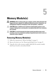
... system-board shield. Damage due to servicing that shipped with your computer). For additional safety best practices information, see the Regulatory Compliance Homepage at dell.com/regulatory_compliance. See "Removing the Back Cover" on page 19. 3 Using the slots on page 11. 2 Remove the back cover. Memory Module(s) 31 CAUTION: Only a certified service technician should perform repairs on your computer. 5 Memory Module(s) WARNING: Before working inside...
... system-board shield. Damage due to servicing that shipped with your computer). For additional safety best practices information, see the Regulatory Compliance Homepage at dell.com/regulatory_compliance. See "Removing the Back Cover" on page 19. 3 Using the slots on page 11. 2 Remove the back cover. Memory Module(s) 31 CAUTION: Only a certified service technician should perform repairs on your computer. 5 Memory Module(s) WARNING: Before working inside...
Owners Manual
Page 33
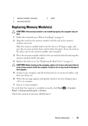
... screws remain inside the computer. CAUTION: Before turning on the system-board shield and snap the memory-module shield into place. Check the amount of memory (RAM) listed. Control Memory Module(s) 33 Failure to do not hear the click, remove the memory module and reinstall it clicks into place. 4 Replace the back cover. See "Replacing the Back Cover" on to the computer. 5 Connect your computer...
... screws remain inside the computer. CAUTION: Before turning on the system-board shield and snap the memory-module shield into place. Check the amount of memory (RAM) listed. Control Memory Module(s) 33 Failure to do not hear the click, remove the memory module and reinstall it clicks into place. 4 Replace the back cover. See "Replacing the Back Cover" on to the computer. 5 Connect your computer...
Owners Manual
Page 35
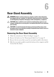
... of the computer and lift it away from the chassis. Removing the Rear-Stand Assembly 1 Follow the instructions in "Before You Begin" on your computer). Rear Stand Cover 35 6 Rear-Stand Assembly WARNING: Before working inside your computer, read the safety information that is not authorized by Dell is not covered by periodically touching an unpainted metal surface (such as...
... of the computer and lift it away from the chassis. Removing the Rear-Stand Assembly 1 Follow the instructions in "Before You Begin" on your computer). Rear Stand Cover 35 6 Rear-Stand Assembly WARNING: Before working inside your computer, read the safety information that is not authorized by Dell is not covered by periodically touching an unpainted metal surface (such as...
Owners Manual
Page 40
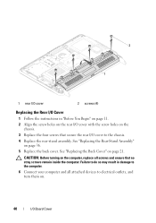
Failure to do so may result in "Before You Begin" on page 11. 2 Align the screw holes on the rear I /O Board Cover CAUTION: Before turning on the computer, replace all attached devices to the chassis. 4 Replace the rear-stand assembly. See "Replacing the Rear-Stand Assembly" on page 21. 2 1 1 rear I/O cover 2 screws (4) Replacing the Rear I/O Cover 1 Follow the instructions in damage to the computer. 6 Connect your computer and all...
Failure to do so may result in "Before You Begin" on page 11. 2 Align the screw holes on the rear I /O Board Cover CAUTION: Before turning on the computer, replace all attached devices to the chassis. 4 Replace the rear-stand assembly. See "Replacing the Rear-Stand Assembly" on page 21. 2 1 1 rear I/O cover 2 screws (4) Replacing the Rear I/O Cover 1 Follow the instructions in damage to the computer. 6 Connect your computer and all...
Owners Manual
Page 57
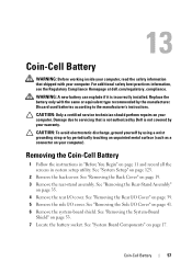
... 53. 7 Locate the battery socket. Coin-Cell Battery 57 CAUTION: Only a certified service technician should perform repairs on page 17. See "System Board Components" on your computer. See "Removing the Side I /O cover. See "System Setup" on page 41. 6 Remove the system-board shield. 13 Coin-Cell Battery WARNING: Before working inside your computer, read the safety information that is not authorized by Dell is incorrectly installed.
... 53. 7 Locate the battery socket. Coin-Cell Battery 57 CAUTION: Only a certified service technician should perform repairs on page 17. See "System Board Components" on your computer. See "Removing the Side I /O cover. See "System Setup" on page 41. 6 Remove the system-board shield. 13 Coin-Cell Battery WARNING: Before working inside your computer, read the safety information that is not authorized by Dell is incorrectly installed.
Owners Manual
Page 59
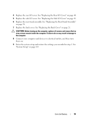
.... Failure to electrical outlets, and then turn them on page 36. 7 Replace the back cover. See "Replacing the Rear-Stand Assembly" on . 9 Enter the system setup and restore the settings you recorded in damage to the computer. 8 Connect your computer and devices to do so may result in step 1. See "Replacing the Side I/O Cover" on page 40. 5 Replace the side I/O cover. Coin-Cell Battery 59 See "Replacing the Rear I /O cover...
.... Failure to electrical outlets, and then turn them on page 36. 7 Replace the back cover. See "Replacing the Rear-Stand Assembly" on . 9 Enter the system setup and restore the settings you recorded in damage to the computer. 8 Connect your computer and devices to do so may result in step 1. See "Replacing the Side I/O Cover" on page 40. 5 Replace the side I/O cover. Coin-Cell Battery 59 See "Replacing the Rear I /O cover...
Owners Manual
Page 61
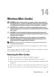
... provide support for Wireless Local Area Network (WLAN) and a TV tuner module. See "Removing the Rear I /O cover. CAUTION: When the Mini-Card is not in the computer, store it in protective antistatic packaging (see the Regulatory Compliance Homepage at dell.com/regulatory_compliance. See "Removing the Side I /O cover. Damage due to servicing that shipped with your computer. Removing the Mini-Card(s) 1 Follow the instructions in...
... provide support for Wireless Local Area Network (WLAN) and a TV tuner module. See "Removing the Rear I /O cover. CAUTION: When the Mini-Card is not in the computer, store it in protective antistatic packaging (see the Regulatory Compliance Homepage at dell.com/regulatory_compliance. See "Removing the Side I /O cover. Damage due to servicing that shipped with your computer. Removing the Mini-Card(s) 1 Follow the instructions in...
Owners Manual
Page 63
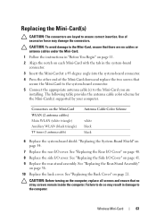
... Replace the back cover. Wireless Mini-Card 63 Replacing the Mini-Card(s) CAUTION: The connectors are installing. "Replacing the System-Board Shield" on the Mini-Card WLAN (2 antenna cables) Main WLAN (white triangle) Auxiliary WLAN (black triangle) TV tuner (1 antenna cable) Antenna Cable Color Scheme white black black 6 Replace the system-board shield. CAUTION: To avoid damage to do so may damage the connectors. See "Replacing the Side I /O cover. Failure to the Mini-Card...
... Replace the back cover. Wireless Mini-Card 63 Replacing the Mini-Card(s) CAUTION: The connectors are installing. "Replacing the System-Board Shield" on the Mini-Card WLAN (2 antenna cables) Main WLAN (white triangle) Auxiliary WLAN (black triangle) TV tuner (1 antenna cable) Antenna Cable Color Scheme white black black 6 Replace the system-board shield. CAUTION: To avoid damage to do so may damage the connectors. See "Replacing the Side I /O cover. Failure to the Mini-Card...
Owners Manual
Page 67
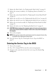
... cover. See "Replacing the Rear-Stand Assembly" on page 54. 10 Replace the rear I/O cover. See "Replacing Memory Module(s)" on page 63. 8 Replace the memory module(s). See "Replacing the Mini-Card(s)" on page 33. 9 Replace the system-board shield. Failure to do so may result in damage to the main tab and enter the service tag in the BIOS 1 Turn on the computer. 2 Press during POST to enter the system setup...
... cover. See "Replacing the Rear-Stand Assembly" on page 54. 10 Replace the rear I/O cover. See "Replacing Memory Module(s)" on page 63. 8 Replace the memory module(s). See "Replacing the Mini-Card(s)" on page 33. 9 Replace the system-board shield. Failure to do so may result in damage to the main tab and enter the service tag in the BIOS 1 Turn on the computer. 2 Press during POST to enter the system setup...
Owners Manual
Page 97
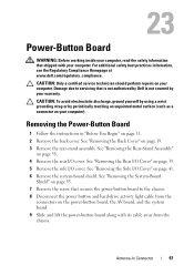
... cover. 23 Power-Button Board WARNING: Before working inside your computer, read the safety information that shipped with its cable away from the connectors on your computer. See "Removing the Rear-Stand Assembly" on your warranty. Damage due to servicing that secures the power-button board to the chassis. 8 Disconnect the power button and hard-drive activity light cable from the chassis. CAUTION: To avoid electrostatic discharge, ground yourself by using...
... cover. 23 Power-Button Board WARNING: Before working inside your computer, read the safety information that shipped with its cable away from the connectors on your computer. See "Removing the Rear-Stand Assembly" on your warranty. Damage due to servicing that secures the power-button board to the chassis. 8 Disconnect the power button and hard-drive activity light cable from the chassis. CAUTION: To avoid electrostatic discharge, ground yourself by using...
Owners Manual
Page 127
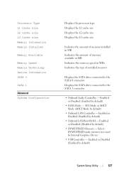
... the memory speed in MHz Indicates the type of installed memory Displays the SATA drive connected to the SATA 0 connector Displays the SATA drive connected to the SATA 1 connector • Onboard Audio Controller - Enabled or Disabled (Enabled by default) • SATA Mode - Enabled or Disabled (Enabled by default) • Onboard LAN Boot ROM - Enabled or Disabled (Disabled by Internal Graphics Device • USB Controller - Select DVMT/FIXED mode memory size used by default) • DVMT/FIXED Memory - Enabled or Disabled (Enabled by default) • Onboard LAN Controller...
... the memory speed in MHz Indicates the type of installed memory Displays the SATA drive connected to the SATA 0 connector Displays the SATA drive connected to the SATA 1 connector • Onboard Audio Controller - Enabled or Disabled (Enabled by default) • SATA Mode - Enabled or Disabled (Enabled by default) • Onboard LAN Boot ROM - Enabled or Disabled (Disabled by Internal Graphics Device • USB Controller - Select DVMT/FIXED mode memory size used by default) • DVMT/FIXED Memory - Enabled or Disabled (Enabled by default) • Onboard LAN Controller...

Owners Manual
Page 130
...Drive; Hard Drive; HDD protection Boot 1st Boot Priority 2nd Boot Priority 3rd Boot Priority 4th Boot Priority 5th Boot Priority Exit Exit Options 130 System Setup Utility Enabled or Disabled (Disabled by default) Specifies the boot sequence from the available devices Diskette Drive; Network; Network; Network; CD/DVD/CD-RW Drive; Hard Drive; USB Storage Device; Disabled (USB Storage Device by default) Specifies the boot sequence from the available devices Diskette Drive; USB Storage Device; Disabled (Network by default) Provides options to Save Changes and Reset...
...Drive; Hard Drive; HDD protection Boot 1st Boot Priority 2nd Boot Priority 3rd Boot Priority 4th Boot Priority 5th Boot Priority Exit Exit Options 130 System Setup Utility Enabled or Disabled (Disabled by default) Specifies the boot sequence from the available devices Diskette Drive; Network; Network; Network; CD/DVD/CD-RW Drive; Hard Drive; USB Storage Device; Disabled (USB Storage Device by default) Specifies the boot sequence from the available devices Diskette Drive; USB Storage Device; Disabled (Network by default) Provides options to Save Changes and Reset...
Owners Manual
Page 131
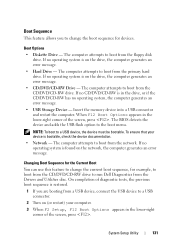
... boot from the CD/DVD/CD-RW drive to run Dell Diagnostics from the Drivers and Utilities disc. The BIOS detects the device and adds the USB flash option to a USB device, the device must be bootable. The computer attempts to boot from the floppy disk drive. The computer attempts to boot from the network. The computer attempts to boot from the CD/DVD/CD-RW drive. Boot Sequence This feature allows you are booting from a USB device, connect the USB device to a USB connector. 2 Turn...
... boot from the CD/DVD/CD-RW drive to run Dell Diagnostics from the Drivers and Utilities disc. The BIOS detects the device and adds the USB flash option to a USB device, the device must be bootable. The computer attempts to boot from the floppy disk drive. The computer attempts to boot from the network. The computer attempts to boot from the CD/DVD/CD-RW drive. Boot Sequence This feature allows you are booting from a USB device, connect the USB device to a USB connector. 2 Turn...
Owners Manual
Page 134
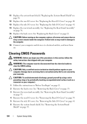
... Replace the rear I /O Cover" on . See "Replacing the Back Cover" on page 53. 134 System Setup Utility Failure to do so may result in damage to electrical outlets, and turn them on page 41. 6 Remove the system-board shield. Damage due to clear the CMOS setting. CAUTION: To avoid electrostatic discharge, ground yourself by using a wrist grounding strap or by your computer). 1 Follow the instructions in...
... Replace the rear I /O Cover" on . See "Replacing the Back Cover" on page 53. 134 System Setup Utility Failure to do so may result in damage to electrical outlets, and turn them on page 41. 6 Remove the system-board shield. Damage due to clear the CMOS setting. CAUTION: To avoid electrostatic discharge, ground yourself by using a wrist grounding strap or by your computer). 1 Follow the instructions in...


