
Owners Manual
Page 7
21 Processor 83 Removing the Processor 83 Replacing the Processor 84 22 Antenna-In Connector 89 Removing the Antenna-In Connector 89 Replacing the Antenna-In Connector 90 23 Antenna Module 93 Removing the Antenna Module 93 Replacing the Antenna Module 94 24 Power-Button Board 97 Removing the Power-Button Board 97 Replacing the Antenna-In Connector 98 25 Speakers 101 Removing the Speakers 101 Replacing the Speakers 102 26 Touch-Screen Control Board (Optional) 105 Removing the Touch-Screen Control Board 105 Contents 7
21 Processor 83 Removing the Processor 83 Replacing the Processor 84 22 Antenna-In Connector 89 Removing the Antenna-In Connector 89 Replacing the Antenna-In Connector 90 23 Antenna Module 93 Removing the Antenna Module 93 Replacing the Antenna Module 94 24 Power-Button Board 97 Removing the Power-Button Board 97 Replacing the Antenna-In Connector 98 25 Speakers 101 Removing the Speakers 101 Replacing the Speakers 102 26 Touch-Screen Control Board (Optional) 105 Removing the Touch-Screen Control Board 105 Contents 7
Owners Manual
Page 8
Replacing the Touch-Screen Control Board. . . . . . 106 27 Display 109 Display Assembly 109 Removing the Display Assembly 109 Replacing the Display Assembly 111 Display Panel 113 Removing the ...
Replacing the Touch-Screen Control Board. . . . . . 106 27 Display 109 Display Assembly 109 Removing the Display Assembly 109 Replacing the Display Assembly 111 Display Panel 113 Removing the ...
Owners Manual
Page 12
... display from being scratched. 2 Turn off your computer). WARNING: Disconnect all attached devices. For additional safety best practices information, see the Regulatory Compliance Homepage at dell.com/regulatory_compliance. WARNING: Before working inside your computer, read the safety information that shipped with locking tabs; CAUTION: To avoid electrostatic discharge, ground yourself by...
... display from being scratched. 2 Turn off your computer). WARNING: Disconnect all attached devices. For additional safety best practices information, see the Regulatory Compliance Homepage at dell.com/regulatory_compliance. WARNING: Before working inside your computer, read the safety information that shipped with locking tabs; CAUTION: To avoid electrostatic discharge, ground yourself by...
Owners Manual
Page 13
Before you work, periodically touch an unpainted metal surface to dissipate static electricity, which could harm internal components. CAUTION: Before touching anything inside your computer, ground yourself by touching an unpainted metal surface, such as the metal at the back of the computer. While you Begin 13
Before you work, periodically touch an unpainted metal surface to dissipate static electricity, which could harm internal components. CAUTION: Before touching anything inside your computer, ground yourself by touching an unpainted metal surface, such as the metal at the back of the computer. While you Begin 13
Owners Manual
Page 15
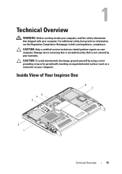
Inside View of Your Inspiron One 45 3 6 7 2 1 Technical Overview 15 For additional safety best practices information, see the Regulatory Compliance Homepage at dell.com/regulatory_compliance. CAUTION: To avoid electrostatic discharge, ground yourself by using a wrist grounding strap or by your warranty. Damage due to ... repairs on your computer). 1 Technical Overview WARNING: Before working inside your computer, read the safety information that is not authorized by Dell is not covered by periodically touching an unpainted metal surface (such as a connector on your computer.
Inside View of Your Inspiron One 45 3 6 7 2 1 Technical Overview 15 For additional safety best practices information, see the Regulatory Compliance Homepage at dell.com/regulatory_compliance. CAUTION: To avoid electrostatic discharge, ground yourself by using a wrist grounding strap or by your warranty. Damage due to ... repairs on your computer). 1 Technical Overview WARNING: Before working inside your computer, read the safety information that is not authorized by Dell is not covered by periodically touching an unpainted metal surface (such as a connector on your computer.
Owners Manual
Page 16
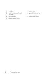
1 hard drive 3 touch-screen control board (optional) 5 camera module 7 memory-module cover 2 optical drive 4 processor heat-sink fan 6 system-board shield 16 Technical Overview
1 hard drive 3 touch-screen control board (optional) 5 camera module 7 memory-module cover 2 optical drive 4 processor heat-sink fan 6 system-board shield 16 Technical Overview
Owners Manual
Page 18
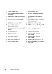
1 SATA connector (ODD) 2 SATA connector (HDD) 3 hard-drive power cable connector (HDD PWR) 4 AV-board cable connector (UMA) 5 display-panel power cable connector 6 touch-screen cable connector (Touch) 7 AV-board cable connector (GPU) 8 power-button and hard-drive activity light cable connector 9 LVDS-cable connector (UMA) 10 LVDS-cable connector (GPU) 11 password...
1 SATA connector (ODD) 2 SATA connector (HDD) 3 hard-drive power cable connector (HDD PWR) 4 AV-board cable connector (UMA) 5 display-panel power cable connector 6 touch-screen cable connector (Touch) 7 AV-board cable connector (GPU) 8 power-button and hard-drive activity light cable connector 9 LVDS-cable connector (UMA) 10 LVDS-cable connector (GPU) 11 password...
Owners Manual
Page 19
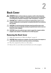
..., see the Regulatory Compliance Homepage at least 30 cm (1 ft.) of desk top space. Damage due to servicing that is not authorized by Dell is not covered by periodically touching an unpainted metal surface (such as a connector on your computer). CAUTION: Only a certified service technician should perform repairs on your computer. 2 Back...
..., see the Regulatory Compliance Homepage at least 30 cm (1 ft.) of desk top space. Damage due to servicing that is not authorized by Dell is not covered by periodically touching an unpainted metal surface (such as a connector on your computer). CAUTION: Only a certified service technician should perform repairs on your computer. 2 Back...
Owners Manual
Page 23
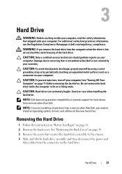
...remove the hard drive while the computer is hot, do not touch the metal housing of the hard drive. NOTE: If you are extremely fragile. CAUTION: Hard drives are installing a hard drive from a source other than Dell, you remove the hard drive from the connector on page 11...instructions in Sleep state. 3 Hard Drive WARNING: Before working inside your computer, read the safety information that is not authorized by Dell is not covered by periodically touching an unpainted metal surface (such as a connector on your computer. CAUTION: To prevent data loss, turn off your computer (...
...remove the hard drive while the computer is hot, do not touch the metal housing of the hard drive. NOTE: If you are extremely fragile. CAUTION: Hard drives are installing a hard drive from a source other than Dell, you remove the hard drive from the connector on page 11...instructions in Sleep state. 3 Hard Drive WARNING: Before working inside your computer, read the safety information that is not authorized by Dell is not covered by periodically touching an unpainted metal surface (such as a connector on your computer. CAUTION: To prevent data loss, turn off your computer (...
Owners Manual
Page 27
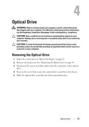
...by your computer). 4 Optical Drive WARNING: Before working inside your computer, read the safety information that is not authorized by Dell is not covered by periodically touching an unpainted metal surface (such as a connector on page 11. 2 Remove the back cover. CAUTION: Only a certified... Follow the instructions in "Before You Begin" on your warranty. For additional safety best practices information, see the Regulatory Compliance Homepage at dell.com/regulatory_compliance. See "Removing the Back Cover" on page 19. 3 Disconnect the power and data cables from the connector on the ...
...by your computer). 4 Optical Drive WARNING: Before working inside your computer, read the safety information that is not authorized by Dell is not covered by periodically touching an unpainted metal surface (such as a connector on page 11. 2 Remove the back cover. CAUTION: Only a certified... Follow the instructions in "Before You Begin" on your warranty. For additional safety best practices information, see the Regulatory Compliance Homepage at dell.com/regulatory_compliance. See "Removing the Back Cover" on page 19. 3 Disconnect the power and data cables from the connector on the ...
Owners Manual
Page 31
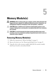
... 11. 2 Remove the back cover. 5 Memory Module(s) WARNING: Before working inside your computer, read the safety information that is not authorized by Dell is not covered by periodically touching an unpainted metal surface (such as a connector on the memory-module shield, lift the memory-module shield away from the system-board shield...
... 11. 2 Remove the back cover. 5 Memory Module(s) WARNING: Before working inside your computer, read the safety information that is not authorized by Dell is not covered by periodically touching an unpainted metal surface (such as a connector on the memory-module shield, lift the memory-module shield away from the system-board shield...
Owners Manual
Page 35
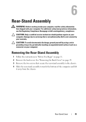
... 11. 2 Remove the back cover. 6 Rear-Stand Assembly WARNING: Before working inside your computer, read the safety information that is not authorized by Dell is not covered by periodically touching an unpainted metal surface (such as a connector on your warranty. CAUTION: Only a certified service technician should perform repairs on your computer. For...
... 11. 2 Remove the back cover. 6 Rear-Stand Assembly WARNING: Before working inside your computer, read the safety information that is not authorized by Dell is not covered by periodically touching an unpainted metal surface (such as a connector on your warranty. CAUTION: Only a certified service technician should perform repairs on your computer. For...
Owners Manual
Page 37
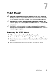
... the chassis. 7 VESA Mount WARNING: Before working inside your computer, read the safety information that is not authorized by Dell is not covered by periodically touching an unpainted metal surface (such as a connector on your computer). See "Removing the Back Cover" on page 11. ...wrist grounding strap or by your computer. VESA Mount 37 For additional safety best practices information, see the Regulatory Compliance Homepage at dell.com/regulatory_compliance. See "Removing the Rear-Stand Assembly" on your warranty. Removing the VESA Mount 1 Follow the instructions in "...
... the chassis. 7 VESA Mount WARNING: Before working inside your computer, read the safety information that is not authorized by Dell is not covered by periodically touching an unpainted metal surface (such as a connector on your computer). See "Removing the Back Cover" on page 11. ...wrist grounding strap or by your computer. VESA Mount 37 For additional safety best practices information, see the Regulatory Compliance Homepage at dell.com/regulatory_compliance. See "Removing the Rear-Stand Assembly" on your warranty. Removing the VESA Mount 1 Follow the instructions in "...
Owners Manual
Page 39
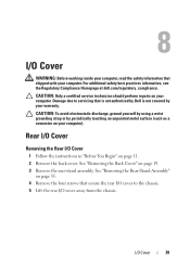
... I/O cover away from the chassis. See "Removing the Rear-Stand Assembly" on page 35. 4 Remove the four screws that is not authorized by Dell is not covered by periodically touching an unpainted metal surface (such as a connector on page 19. 3 Remove the rear-stand assembly. Rear I/O Cover Removing the Rear I/O Cover 1 Follow...
... I/O cover away from the chassis. See "Removing the Rear-Stand Assembly" on page 35. 4 Remove the four screws that is not authorized by Dell is not covered by periodically touching an unpainted metal surface (such as a connector on page 19. 3 Remove the rear-stand assembly. Rear I/O Cover Removing the Rear I/O Cover 1 Follow...
Owners Manual
Page 43
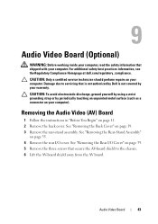
...) WARNING: Before working inside your computer, read the safety information that secure the AV-board shield to servicing that is not authorized by Dell is not covered by periodically touching an unpainted metal surface (such as a connector on page 19. 3 Remove the rear-stand assembly. See "Removing the Back Cover" on your... a certified service technician should perform repairs on page 11. 2 Remove the back cover. For additional safety best practices information, see the Regulatory Compliance Homepage at dell.com/regulatory_compliance.
...) WARNING: Before working inside your computer, read the safety information that secure the AV-board shield to servicing that is not authorized by Dell is not covered by periodically touching an unpainted metal surface (such as a connector on page 19. 3 Remove the rear-stand assembly. See "Removing the Back Cover" on your... a certified service technician should perform repairs on page 11. 2 Remove the back cover. For additional safety best practices information, see the Regulatory Compliance Homepage at dell.com/regulatory_compliance.
Owners Manual
Page 47
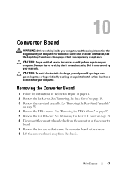
For additional safety best practices information, see the Regulatory Compliance Homepage at dell.com/regulatory_compliance. Damage due to the chassis. 8 Lift the converter board away from the connector on the converter board. 7 Remove the two screws that secure ... a wrist grounding strap or by your warranty. 10 Converter Board WARNING: Before working inside your computer, read the safety information that is not authorized by Dell is not covered by periodically touching an unpainted metal surface (such as a connector on your computer. See "Removing the Rear I /O cover.
For additional safety best practices information, see the Regulatory Compliance Homepage at dell.com/regulatory_compliance. Damage due to the chassis. 8 Lift the converter board away from the connector on the converter board. 7 Remove the two screws that secure ... a wrist grounding strap or by your warranty. 10 Converter Board WARNING: Before working inside your computer, read the safety information that is not authorized by Dell is not covered by periodically touching an unpainted metal surface (such as a connector on your computer. See "Removing the Rear I /O cover.
Owners Manual
Page 51
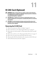
For additional safety best practices information, see the Regulatory Compliance Homepage at www.dell.com/regulatory_compliance. See "Removing the Rear-Stand Assembly" on page 11. 2 Remove the back cover. Damage due to the chassis. 6 Disconnect the B-CAS card cable .... 4 Remove the rear I /O Cover" on page 39. 5 Remove the screw that secures the B-CAS card to servicing that is not authorized by Dell is not covered by periodically touching an unpainted metal surface (such as a connector on the B-CAS card. 7 Lift the B-CAS card away from the computer. See "Removing the Rear...
For additional safety best practices information, see the Regulatory Compliance Homepage at www.dell.com/regulatory_compliance. See "Removing the Rear-Stand Assembly" on page 11. 2 Remove the back cover. Damage due to the chassis. 6 Disconnect the B-CAS card cable .... 4 Remove the rear I /O Cover" on page 39. 5 Remove the screw that secures the B-CAS card to servicing that is not authorized by Dell is not covered by periodically touching an unpainted metal surface (such as a connector on the B-CAS card. 7 Lift the B-CAS card away from the computer. See "Removing the Rear...
Owners Manual
Page 53
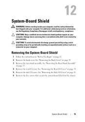
...4 Remove the rear I /O cover. System-Board Shield 53 For additional safety best practices information, see the Regulatory Compliance Homepage at dell.com/regulatory_compliance. See "Removing the Rear-Stand Assembly" on page 11. 2 Remove the back cover. 12 System-Board Shield WARNING:... Before working inside your computer, read the safety information that is not authorized by Dell is not covered by periodically touching an unpainted metal surface (such as a connector on your computer. CAUTION: To avoid electrostatic discharge, ground yourself ...
...4 Remove the rear I /O cover. System-Board Shield 53 For additional safety best practices information, see the Regulatory Compliance Homepage at dell.com/regulatory_compliance. See "Removing the Rear-Stand Assembly" on page 11. 2 Remove the back cover. 12 System-Board Shield WARNING:... Before working inside your computer, read the safety information that is not authorized by Dell is not covered by periodically touching an unpainted metal surface (such as a connector on your computer. CAUTION: To avoid electrostatic discharge, ground yourself ...
Owners Manual
Page 57
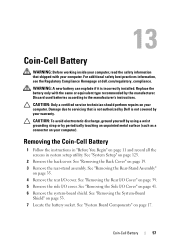
... 19. 3 Remove the rear-stand assembly. CAUTION: To avoid electrostatic discharge, ground yourself by using a wrist grounding strap or by periodically touching an unpainted metal surface (such as a connector on page 125. 2 Remove the back cover. See "System Setup" on your computer)....Damage due to the manufacturer's instructions. Coin-Cell Battery 57 For additional safety best practices information, see the Regulatory Compliance Homepage at dell.com/regulatory_compliance. See "Removing the Rear I /O cover. 13 Coin-Cell Battery WARNING: Before working inside your computer, read the...
... 19. 3 Remove the rear-stand assembly. CAUTION: To avoid electrostatic discharge, ground yourself by using a wrist grounding strap or by periodically touching an unpainted metal surface (such as a connector on page 125. 2 Remove the back cover. See "System Setup" on your computer)....Damage due to the manufacturer's instructions. Coin-Cell Battery 57 For additional safety best practices information, see the Regulatory Compliance Homepage at dell.com/regulatory_compliance. See "Removing the Rear I /O cover. 13 Coin-Cell Battery WARNING: Before working inside your computer, read the...
Owners Manual
Page 58
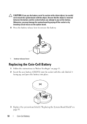
... release lever Replacing the Coin-Cell Battery 1 Follow the instructions in "Before You Begin" on page 54. 58 Coin-Cell Battery Otherwise, you attempt to touch the system board with the object.
... release lever Replacing the Coin-Cell Battery 1 Follow the instructions in "Before You Begin" on page 54. 58 Coin-Cell Battery Otherwise, you attempt to touch the system board with the object.


