
Owners Manual
Page 7
21 Processor 83 Removing the Processor 83 Replacing the Processor 84 22 Antenna-In Connector 89 Removing the Antenna-In Connector 89 Replacing the Antenna-In Connector 90 23 Antenna Module 93 Removing the Antenna Module 93 Replacing the Antenna Module 94 24 Power-Button Board 97 Removing the Power-Button Board 97 Replacing the Antenna-In Connector 98 25 Speakers 101 Removing the Speakers 101 Replacing the Speakers 102 26 Touch-Screen Control Board (Optional) 105 Removing the Touch-Screen Control Board 105 Contents 7
21 Processor 83 Removing the Processor 83 Replacing the Processor 84 22 Antenna-In Connector 89 Removing the Antenna-In Connector 89 Replacing the Antenna-In Connector 90 23 Antenna Module 93 Removing the Antenna Module 93 Replacing the Antenna Module 94 24 Power-Button Board 97 Removing the Power-Button Board 97 Replacing the Antenna-In Connector 98 25 Speakers 101 Removing the Speakers 101 Replacing the Speakers 102 26 Touch-Screen Control Board (Optional) 105 Removing the Touch-Screen Control Board 105 Contents 7
Owners Manual
Page 8
Replacing the Touch-Screen Control Board. . . . . . 106 27 Display 109 Display Assembly 109 Removing the Display Assembly 109 Replacing the Display Assembly 111 Display Panel 113 Removing the Display Panel 113 Replacing the Display Panel 113 Display-Panel Brackets 114 Removing the Display-Panel Brackets 114 Replacing... the Display-Panel Brackets 115 28 Camera Module 117 Removing the Camera Module 117 Replacing the Camera Module 118 29 ...
Replacing the Touch-Screen Control Board. . . . . . 106 27 Display 109 Display Assembly 109 Removing the Display Assembly 109 Replacing the Display Assembly 111 Display Panel 113 Removing the Display Panel 113 Replacing the Display Panel 113 Display-Panel Brackets 114 Removing the Display-Panel Brackets 114 Replacing... the Display-Panel Brackets 115 28 Camera Module 117 Removing the Camera Module 117 Replacing the Camera Module 118 29 ...
Owners Manual
Page 57
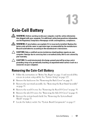
For additional safety best practices information, see the Regulatory Compliance Homepage at dell.com/regulatory_compliance. Replace the battery only with your computer. See "Removing the Back Cover" on page 17. See "Removing the Side I /O cover. See "System Board Components" on page... in "Before You Begin" on page 35. 4 Remove the rear I/O cover. See "Removing the Rear-Stand Assembly" on page 11 and record all the screens in system setup utility. WARNING: A new battery can explode if it is not covered by your warranty. See "Removing the System-Board Shield" on your...
For additional safety best practices information, see the Regulatory Compliance Homepage at dell.com/regulatory_compliance. Replace the battery only with your computer. See "Removing the Back Cover" on page 17. See "Removing the Side I /O cover. See "System Board Components" on page... in "Before You Begin" on page 35. 4 Remove the rear I/O cover. See "Removing the Rear-Stand Assembly" on page 11 and record all the screens in system setup utility. WARNING: A new battery can explode if it is not covered by your warranty. See "Removing the System-Board Shield" on your...
Owners Manual
Page 106
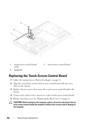
... 11. 2 Align the screw holes on the touch-screen control board with the screw holes on the chassis. 3 Replace the two screws that no stray screws remain inside the computer. See "Replacing the Back Cover" on the computer, replace all screws and ensure that secure the touch-screen control board to the chassis. 4 Connect the...
... 11. 2 Align the screw holes on the touch-screen control board with the screw holes on the chassis. 3 Replace the two screws that no stray screws remain inside the computer. See "Replacing the Back Cover" on the computer, replace all screws and ensure that secure the touch-screen control board to the chassis. 4 Connect the...
Owners Manual
Page 111
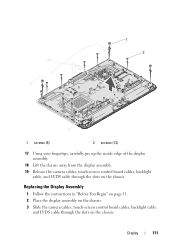
Display 111 Replacing the Display Assembly 1 Follow the instructions in "Before You Begin" on page 11. 2 Place the display assembly on the chassis. 3 Slide the camera cables, touch-screen control board cables, backlight cable and LVDS cable through the slots on the chassis. 1 2 1 screws (5) 2 screws (13) 17 Using your fingertips, carefully pry up the inside edge of the display assembly. 18 Lift the chassis away from the display assembly. 19 Release the camera cables, touch-screen control board cables, backlight cable, and LVDS cable through the slots on the chassis.
Display 111 Replacing the Display Assembly 1 Follow the instructions in "Before You Begin" on page 11. 2 Place the display assembly on the chassis. 3 Slide the camera cables, touch-screen control board cables, backlight cable and LVDS cable through the slots on the chassis. 1 2 1 screws (5) 2 screws (13) 17 Using your fingertips, carefully pry up the inside edge of the display assembly. 18 Lift the chassis away from the display assembly. 19 Release the camera cables, touch-screen control board cables, backlight cable, and LVDS cable through the slots on the chassis.
Owners Manual
Page 112
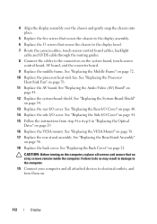
... cables to the connectors on page 29. 16 Replace the VESA mount. See "Replacing the Side I /O cover. See "Replacing the Back Cover" on page 45. 12 Replace the system-board shield. Failure to do so may result in "Replacing the Optical Drive" on the system board, touch-screen control board, AV board, and the converter board...
... cables to the connectors on page 29. 16 Replace the VESA mount. See "Replacing the Side I /O cover. See "Replacing the Back Cover" on page 45. 12 Replace the system-board shield. Failure to do so may result in "Replacing the Optical Drive" on the system board, touch-screen control board, AV board, and the converter board...
Owners Manual
Page 137
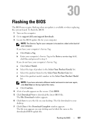
... appears. The File Download window appears. 6 Click Save to save the file on a label at the back of your desktop and is available or when replacing the system board. b Select the type of the menu. c Select the product brand in the Enter a service tag: field, click Go, and proceed to... start over again, click Start Over on the screen. Click BIOS. 5 Click Download Now to support.dell.com/support/downloads. 3 Locate the BIOS update file for your computer: NOTE: The Service Tag for your computer is located on your...
... appears. The File Download window appears. 6 Click Save to save the file on a label at the back of your desktop and is available or when replacing the system board. b Select the type of the menu. c Select the product brand in the Enter a service tag: field, click Go, and proceed to... start over again, click Start Over on the screen. Click BIOS. 5 Click Download Now to support.dell.com/support/downloads. 3 Locate the BIOS update file for your computer: NOTE: The Service Tag for your computer is located on your...


