
Owners Manual
Page 3
Contents 1 Before You Begin 11 Recommended Tools 11 Turning Off Your Computer 11 Safety Instructions 11 2 Technical Overview 15 Inside View of Your Inspiron One 15 System Board Components 17 3 Back Cover 19 Removing the Back Cover 19 Replacing the Back Cover 21 4 Hard Drive 23 Removing the Hard Drive 23 Replacing the Hard Drive 25 5 Optical Drive 27 Removing the Optical Drive 27 Contents 3
Contents 1 Before You Begin 11 Recommended Tools 11 Turning Off Your Computer 11 Safety Instructions 11 2 Technical Overview 15 Inside View of Your Inspiron One 15 System Board Components 17 3 Back Cover 19 Removing the Back Cover 19 Replacing the Back Cover 21 4 Hard Drive 23 Removing the Hard Drive 23 Replacing the Hard Drive 25 5 Optical Drive 27 Removing the Optical Drive 27 Contents 3
Owners Manual
Page 16
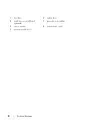
1 hard drive 3 touch-screen control board (optional) 5 camera module 7 memory-module cover 2 optical drive 4 processor heat-sink fan 6 system-board shield 16 Technical Overview
1 hard drive 3 touch-screen control board (optional) 5 camera module 7 memory-module cover 2 optical drive 4 processor heat-sink fan 6 system-board shield 16 Technical Overview
Owners Manual
Page 18
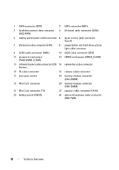
... (HDD PWR) 4 AV-board cable connector (UMA) 5 display-panel power cable connector 6 touch-screen cable connector (Touch) 7 AV-board cable connector (GPU) 8 power-button and hard-drive activity light cable connector 9 LVDS-cable connector (UMA) 10 LVDS-cable connector (GPU) 11 password reset jumper (PASSWORD_CLEAR) 12 CMOS reset jumper (CMOS_CLEAR) 13 infrared...-Card connector 20 memory-module connector (CHB-DIMM) 21 Mini-Card connector (TV) 22 speaker-cable connector (CN 10) 23 battery socket (CMOS) 24 optical-drive power cable connector (ODD PWR) 18 Technical Overview
... (HDD PWR) 4 AV-board cable connector (UMA) 5 display-panel power cable connector 6 touch-screen cable connector (Touch) 7 AV-board cable connector (GPU) 8 power-button and hard-drive activity light cable connector 9 LVDS-cable connector (UMA) 10 LVDS-cable connector (GPU) 11 password reset jumper (PASSWORD_CLEAR) 12 CMOS reset jumper (CMOS_CLEAR) 13 infrared...-Card connector 20 memory-module connector (CHB-DIMM) 21 Mini-Card connector (TV) 22 speaker-cable connector (CN 10) 23 battery socket (CMOS) 24 optical-drive power cable connector (ODD PWR) 18 Technical Overview
Owners Manual
Page 23
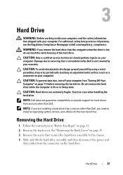
... or in "Before You Begin" on the new hard drive. Exercise care when handling the hard drive. Hard Drive 23 Do not remove the hard drive while the computer is not covered by your warranty. CAUTION: Hard drives are installing a hard drive from a source other than Dell, you remove the hard drive from the computer when the drive is hot, do not touch the metal housing...
... or in "Before You Begin" on the new hard drive. Exercise care when handling the hard drive. Hard Drive 23 Do not remove the hard drive while the computer is not covered by your warranty. CAUTION: Hard drives are installing a hard drive from a source other than Dell, you remove the hard drive from the computer when the drive is hot, do not touch the metal housing...
Owners Manual
Page 24
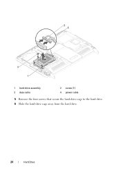
34 2 1 1 hard-drive assembly 3 data cable 2 screw (1) 4 power cable 5 Remove the four screws that secure the hard-drive cage to the hard drive. 6 Slide the hard-drive cage away from the hard drive. 24 Hard Drive
34 2 1 1 hard-drive assembly 3 data cable 2 screw (1) 4 power cable 5 Remove the four screws that secure the hard-drive cage to the hard drive. 6 Slide the hard-drive cage away from the hard drive. 24 Hard Drive
Owners Manual
Page 25
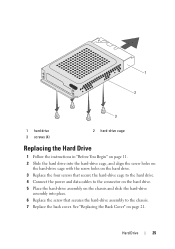
... the chassis and slide the hard-drive assembly into the hard-drive cage, and align the screw holes on the hard-drive cage with the screw holes on the hard drive. 3 Replace the four screws that secures the hard-drive assembly to the connector on the hard drive. 5 Place the hard-drive assembly on page 21. 1 2 3 1 hard drive 3 screws (4) 2 hard-drive cage Replacing the Hard Drive 1 Follow the instructions in...
... the chassis and slide the hard-drive assembly into the hard-drive cage, and align the screw holes on the hard-drive cage with the screw holes on the hard drive. 3 Replace the four screws that secures the hard-drive assembly to the connector on the hard drive. 5 Place the hard-drive assembly on page 21. 1 2 3 1 hard drive 3 screws (4) 2 hard-drive cage Replacing the Hard Drive 1 Follow the instructions in...
Owners Manual
Page 26
Failure to do so may result in damage to the computer. 8 Connect your computer and all attached devices to electrical outlets, and turn them on the computer, replace all screws and ensure that no stray screws remain inside the computer. CAUTION: Before turning on . 26 Hard Drive
Failure to do so may result in damage to the computer. 8 Connect your computer and all attached devices to electrical outlets, and turn them on the computer, replace all screws and ensure that no stray screws remain inside the computer. CAUTION: Before turning on . 26 Hard Drive
Owners Manual
Page 97
...and lift the power-button board along with your warranty. Antenna-In Connector 97 Damage due to the chassis. 8 Disconnect the power button and hard-drive activity light cable from the chassis. See "Removing the System-Board Shield" on page 53. 7 Remove the screw that secures the power-button ...board to servicing that is not authorized by Dell is not covered by periodically touching an unpainted metal surface (such as a connector on page 35. 4 Remove the rear I /O Cover" on page...
...and lift the power-button board along with your warranty. Antenna-In Connector 97 Damage due to the chassis. 8 Disconnect the power button and hard-drive activity light cable from the chassis. See "Removing the System-Board Shield" on page 53. 7 Remove the screw that secures the power-button ...board to servicing that is not authorized by Dell is not covered by periodically touching an unpainted metal surface (such as a connector on page 35. 4 Remove the rear I /O Cover" on page...
Owners Manual
Page 98
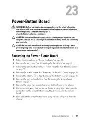
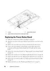
... I/O Cover" on the power-button board, the AV board, and the system board. 5 Replace the system-board shield. 1 2 3 1 screw 2 power-button board 3 power-button and hard-drive activity light cable Replacing the Power-Button Board 1 Follow the instructions in "Before You Begin" on page 11. 2 Align the screw hole on the power... board with the screw hole on the chassis. 3 Replace the screw that secures the power-button board to the chassis. 4 Connect the power button and hard-drive activity light cable to the connectors on page 40. 7 Replace the side I/O cover.
... I/O Cover" on the power-button board, the AV board, and the system board. 5 Replace the system-board shield. 1 2 3 1 screw 2 power-button board 3 power-button and hard-drive activity light cable Replacing the Power-Button Board 1 Follow the instructions in "Before You Begin" on page 11. 2 Align the screw hole on the power... board with the screw hole on the chassis. 3 Replace the screw that secures the power-button board to the chassis. 4 Connect the power button and hard-drive activity light cable to the connectors on page 40. 7 Replace the side I/O cover.
Owners Manual
Page 125
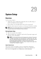
...See "Turning Off Your Computer" on the screen is recommended that the keyboard has initialized. Then, turn off your computer. 2 When the DELL logo is lost. System Setup Screens The system setup screen displays current or changeable configuration information for it is divided into three areas: the ...• Set or change a user-selectable option such as the user password • Read the current amount of memory or set the type of hard drive installed NOTE: Before you change system setup, it , and then press . This prompt can appear very quickly, so you must watch for future...
...See "Turning Off Your Computer" on the screen is recommended that the keyboard has initialized. Then, turn off your computer. 2 When the DELL logo is lost. System Setup Screens The system setup screen displays current or changeable configuration information for it is divided into three areas: the ...• Set or change a user-selectable option such as the user password • Read the current amount of memory or set the type of hard drive installed NOTE: Before you change system setup, it , and then press . This prompt can appear very quickly, so you must watch for future...

Owners Manual
Page 130
... boot sequence from the available devices Diskette Drive; CD/DVD/CD-RW Drive; USB Storage Device; CD/DVD/CD-RW Drive; CD/DVD/CD-RW Drive; Network; Hard Drive; USB Storage Device; CD/DVD/CD-RW Drive; Network; Disabled (Hard Drive by default) Specifies the boot sequence from the available devices Diskette Drive; Hard Drive; USB Storage Device; Disabled (Network by default...
... boot sequence from the available devices Diskette Drive; CD/DVD/CD-RW Drive; USB Storage Device; CD/DVD/CD-RW Drive; CD/DVD/CD-RW Drive; Network; Hard Drive; USB Storage Device; CD/DVD/CD-RW Drive; Network; Disabled (Hard Drive by default) Specifies the boot sequence from the available devices Diskette Drive; Hard Drive; USB Storage Device; Disabled (Network by default...
Owners Manual
Page 131
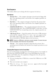
...CD-RW is found on the drive, the computer generates an error message. • Hard Drive - Changing Boot Sequence for the Current Boot You can use this feature to change the boot sequence for example, to boot from the CD/DVD/CD-RW drive to run Dell Diagnostics from the Drivers and ...Utilities disc. Boot Options • Diskette Drive - Insert the memory device...
...CD-RW is found on the drive, the computer generates an error message. • Hard Drive - Changing Boot Sequence for the Current Boot You can use this feature to change the boot sequence for example, to boot from the CD/DVD/CD-RW drive to run Dell Diagnostics from the Drivers and ...Utilities disc. Boot Options • Diskette Drive - Insert the memory device...


