
Dell Inspiron One 2320 Support Question
Dell Inspiron One 2320 Support Question
Find answers below for this question about Dell Inspiron One 2320.Need a Dell Inspiron One 2320 manual? We have 3 online manuals for this item!
Question posted by rsmith90 on May 11th, 2012
How Do I Take Off Back Yo Replace Memory And Hard Drive On Insprion2320
The person who posted this question about this Dell product did not include a detailed explanation. Please use the "Request More Information" button to the right if more details would help you to answer this question.
Current Answers
Answer #1: Posted by DellJesse1 on May 11th, 2012 9:37 AM
DellJesse1

Member since:
April 19th, 2012 Points: 1,551,500

Member since:
April 19th, 2012 Points: 1,551,500
rsmith90,
You can click the link below to download the online manual for removing and replacing parts on your Inspiron 2320.
Thank You,
Dell-Jesse1
Dell Social Media and Communities
email:[email protected]
Dell Community Forum.
www.en.community.dell.com
Dell Twitter Support
@dellcares
Dell Facebook Support
www.facebook.com/dell
#iwork4dell
Related Dell Inspiron One 2320 Manual Pages
Owners Manual - Page 3
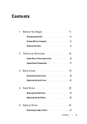
... You Begin 11
Recommended Tools 11 Turning Off Your Computer 11 Safety Instructions 11
2 Technical Overview 15
Inside View of Your Inspiron One 15 System Board Components 17
3 Back Cover 19
Removing the Back Cover 19 Replacing the Back Cover 21
4 Hard Drive 23
Removing the Hard Drive 23 Replacing the Hard Drive 25
5 Optical Drive 27
Removing the Optical...
Owners Manual - Page 4
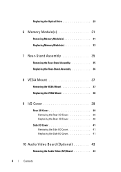
Replacing the Optical Drive 29
6 Memory Module(s 31
Removing Memory Module(s 31 Replacing Memory Module(s 33
7 Rear-Stand Assembly 35
Removing the Rear-Stand Assembly 35 Replacing the Rear-Stand Assembly 36
8 VESA Mount 37
Removing the VESA Mount 37 Replacing the VESA Mount 38
9 I/O Cover 39
Rear I/O Cover 39 Removing the Rear I/O Cover 39 Replacing the Rear I/O Cover 40...
Owners Manual - Page 16
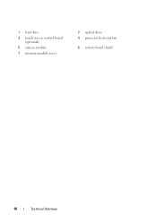
1 hard drive 3 touch-screen control board
(optional) 5 camera module 7 memory-module cover
2 optical drive 4 processor heat-sink fan
6 system-board shield
16
Technical Overview
Owners Manual - Page 18
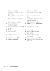
... 6 touch-screen cable connector (Touch)
7 AV-board cable connector (GPU)
8 power-button and hard-drive activity light cable connector
9 LVDS-cable connector (UMA)
10 LVDS-cable connector (GPU)
11 password ... connector
16 camera-cable connector
17 processor socket
18 memory-module connector (CHA-DIMM)
19 Mini-Card connector
20 memory-module connector (CHB-DIMM)
21 Mini-Card connector ...
Owners Manual - Page 23
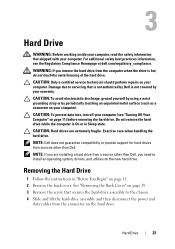
... sources other than Dell. CAUTION: To prevent data loss, turn off your computer (see the Regulatory Compliance Homepage at dell.com/regulatory_compliance. CAUTION: Hard drives are installing a hard drive from the connector on your computer). NOTE: If you need to servicing that is not authorized by Dell is not covered by periodically touching an...
Owners Manual - Page 24
34
2 1
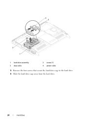
1 hard-drive assembly 3 data cable
2 screw (1) 4 power cable
5 Remove the four screws that secure the hard-drive cage to the hard drive. 6 Slide the hard-drive cage away from the hard drive.
24
Hard Drive
Owners Manual - Page 25
Hard Drive
25 1 2
3
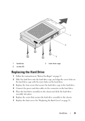
1 hard drive 3 screws (4)
2 hard-drive cage
Replacing the Hard Drive
1 Follow the instructions in "Before You Begin" on page 11. 2 Slide the hard drive into place. 6 Replace the screw that secure the hard-drive cage to the hard drive. 4 Connect the power and data cables to the connector on the hard drive. 5 Place the hard-drive assembly on page 21.
See "Replacing ...
Owners Manual - Page 26
CAUTION: Before turning on .
26
Hard Drive Failure to do so may result in damage to the computer.
8 Connect your computer and all attached devices to electrical outlets, and turn them on the computer, replace all screws and ensure that no stray screws remain inside the computer.
Owners Manual - Page 29
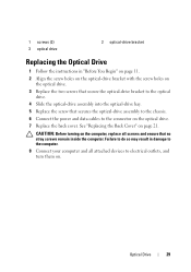
... bracket with the screw holes on
the optical drive. 3 Replace the two screws that secure the optical-drive bracket to the optical
drive. 4 Slide the optical-drive assembly into the optical-drive bay. 5 Replace the screw that no stray screws remain inside the computer. 1 screws (2) 3 optical drive
2 optical-drive bracket
Replacing the Optical Drive
1 Follow the instructions in damage to the...
Owners Manual - Page 33
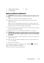
... changed, press to continue.
7 Log on the system-board shield and snap the memory-module shield into place. Check the amount of memory (RAM) listed.
Control
Memory Module(s)
33 1 memory-module connector 3 securing clips (2)
2 notch
Replacing Memory Module(s)
CAUTION: If the memory module is installed correctly, click Start PanelSystem and Security...
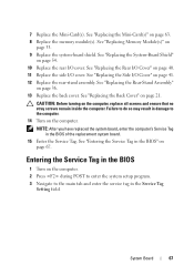
Owners Manual - Page 67
...
1 Turn on
page 67. See "Replacing the Back Cover" on page 54. 10 Replace the rear I/O cover.
See "Replacing the Mini-Card(s)" on
page 33. 9 Replace the system-board shield. See "Replacing Memory Module(s)" on page 63. 8 Replace the memory module(s). 7 Replace the Mini-Card(s). See "Replacing the Rear-Stand Assembly"
on the computer, replace all screws and ensure that no...
Owners Manual - Page 72

... on the middle frame with the tabs on the chassis. 3 Align the screw holes on the middle frame with the screw holes on the
chassis. 4 Replace the 11 screws that secure the middle frame to step 6 in "Replacing the Optical
Drive" on page 29. 7 Replace the system-board shield.
Owners Manual - Page 95
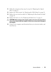
... cover.
CAUTION: Before turning on the computer, replace all attached devices to the computer. 15 Connect your computer and all screws and ensure that no stray screws remain inside the computer. Failure to do so may result in "Replacing the Optical Drive" on page 21. See "Replacing the Rear-Stand Assembly"
on page 38...
Owners Manual - Page 97
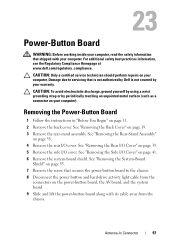
...: To avoid electrostatic discharge, ground yourself by using a wrist grounding strap or by your warranty.
Damage due to the chassis. 8 Disconnect the power button and hard-drive activity light cable from the
connectors on your computer. See "Removing the Side I /O cover. Removing the Power-Button Board
1 Follow the instructions in "Before You...
Owners Manual - Page 98
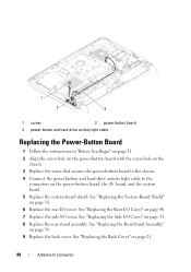
... to the chassis. 4 Connect the power button and hard-drive activity light cable to the
connectors on page 54. 6 Replace the rear I/O cover. See "Replacing the System-Board Shield" on the power-button board, the AV board, and the system board. 5 Replace the system-board shield. See "Replacing the Side I/O Cover" on page 21.
98
Antenna...
Owners Manual - Page 112
... system-board shield.
Failure to do so may result in "Replacing the Optical
Drive" on page 40. 14 Replace the side I /O cover. See "Replacing the Audio Video (AV) Board" on page 38. 17 Replace the rear-stand assembly. See "Replacing the Side I/O Cover" on page 41. 15 Follow the instructions from step 4 to the connectors on...
Owners Manual - Page 123
... stray screws remain inside the computer. See "Replacing the Side I /O cover. See "Replacing the VESA Mount" on page 21. See "Replacing the Rear-Stand Assembly"
on the computer, replace all attached devices to step 6 in "Replacing the Optical
Drive" on page 29. 11 Replace the VESA mount. Speaker Cover
123 9 Replace the side I /O Cover" on page 41. 10...
Owners Manual - Page 125
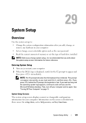
If you see the Microsoft Windows desktop. If you wait too long and the operating system logo appears, continue to wait until you... computer • Set or change a user-selectable option such as the user password • Read the current amount of memory or set the type of hard drive installed
NOTE: Before you change system setup, it , and then press . Entering System Setup
1 Turn on (or restart...
Owners Manual - Page 130

... the boot sequence from the available devices Diskette Drive; Disabled (Hard Drive by default) Specifies the boot sequence from the available devices Diskette Drive; Network; Hard Drive; Network; Hard Drive; CD/DVD/CD-RW Drive; Disabled (Network by default)
Specifies the boot sequence from the available devices Diskette Drive; Hard Drive; Network; HDD protection
Boot 1st Boot...
Owners Manual - Page 131
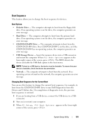
...devices. Insert the memory device into a USB connector and restart the computer. The computer attempts to change the boot sequence for example, to boot from the CD/DVD/CD-RW drive to run Dell ...CD-RW is found on the drive, the computer generates an error message. • Hard Drive - To ensure that your computer. 3 When F2 Setup, F12 Boot Options appears in the drive, or if the CD/DVD...
Similar Questions

Is It Possible To Replace Graphics Card On Dell 2420 Inspiron
(Posted by heeleg 9 years ago)

How To Replace The Hard Drive From Dell Poweredge R810 Model
(Posted by Perciecharm2 10 years ago)

How To Get To Hard Drive On Dell Inspiron 2320
(Posted by Durisifer 10 years ago)


How To Replace The Hard Drive On The Inspiron One 2305 Computer
(Posted by lieram21 10 years ago)