
Owners Manual
Page 4
Replacing the Optical Drive 29 6 Memory Module(s 31 Removing Memory Module(s 31 Replacing Memory Module(s 33 7 Rear-Stand Assembly 35 Removing the Rear-Stand Assembly 35 Replacing the Rear-Stand Assembly 36 8 VESA Mount 37 Removing the VESA Mount 37 Replacing the VESA Mount 38 9 I/O Cover 39 Rear I/O Cover 39 Removing the Rear I/O Cover 39 Replacing the Rear I/O Cover 40 Side I/O Cover 41 Removing the Side I/O Cover 41 Replacing the Side I/O Cover 41 10 Audio Video Board (Optional 43 Removing the Audio Video (AV) Board 43 4 Contents
Replacing the Optical Drive 29 6 Memory Module(s 31 Removing Memory Module(s 31 Replacing Memory Module(s 33 7 Rear-Stand Assembly 35 Removing the Rear-Stand Assembly 35 Replacing the Rear-Stand Assembly 36 8 VESA Mount 37 Removing the VESA Mount 37 Replacing the VESA Mount 38 9 I/O Cover 39 Rear I/O Cover 39 Removing the Rear I/O Cover 39 Replacing the Rear I/O Cover 40 Side I/O Cover 41 Removing the Side I/O Cover 41 Replacing the Side I/O Cover 41 10 Audio Video Board (Optional 43 Removing the Audio Video (AV) Board 43 4 Contents
Owners Manual
Page 16
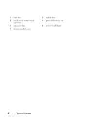
1 hard drive 3 touch-screen control board (optional) 5 camera module 7 memory-module cover 2 optical drive 4 processor heat-sink fan 6 system-board shield 16 Technical Overview
1 hard drive 3 touch-screen control board (optional) 5 camera module 7 memory-module cover 2 optical drive 4 processor heat-sink fan 6 system-board shield 16 Technical Overview
Owners Manual
Page 18
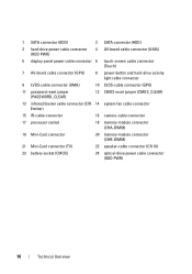
... cable connector (CIR 14 system-fan cable connector Emitter) 15 IR-cable connector 16 camera-cable connector 17 processor socket 18 memory-module connector (CHA-DIMM) 19 Mini-Card connector 20 memory-module connector (CHB-DIMM) 21 Mini-Card connector (TV) 22 speaker-cable connector (CN 10) 23 battery socket (CMOS) 24...
... cable connector (CIR 14 system-fan cable connector Emitter) 15 IR-cable connector 16 camera-cable connector 17 processor socket 18 memory-module connector (CHA-DIMM) 19 Mini-Card connector 20 memory-module connector (CHB-DIMM) 21 Mini-Card connector (TV) 22 speaker-cable connector (CN 10) 23 battery socket (CMOS) 24...
Owners Manual
Page 31
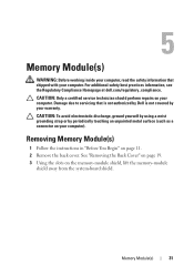
Damage due to servicing that shipped with your computer. Memory Module(s) 31 5 Memory Module(s) WARNING: Before working inside your computer, read the safety information that is not authorized by Dell is not covered by periodically touching an unpainted metal surface (such as a connector on your computer). CAUTION: Only a certified service technician should perform repairs...
Damage due to servicing that shipped with your computer. Memory Module(s) 31 5 Memory Module(s) WARNING: Before working inside your computer, read the safety information that is not authorized by Dell is not covered by periodically touching an unpainted metal surface (such as a connector on your computer). CAUTION: Only a certified service technician should perform repairs...
Owners Manual
Page 32
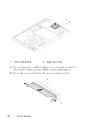
1 2 1 memory-module shield 2 system-board shield 4 Use your fingertips to carefully spread apart the securing clips on each end of the memory-module connector until the memory module pops up. 5 Remove the memory module from the memory-module connector. 1 2 3 32 Memory Module(s)
1 2 1 memory-module shield 2 system-board shield 4 Use your fingertips to carefully spread apart the securing clips on each end of the memory-module connector until the memory module pops up. 5 Remove the memory module from the memory-module connector. 1 2 3 32 Memory Module(s)
Owners Manual
Page 33
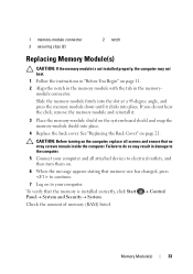
...into place. 4 Replace the back cover. Check the amount of memory (RAM) listed. Control Memory Module(s) 33 Failure to the computer. 5 Connect your computer. To verify that the memory is not installed properly, the computer may result in the memorymodule ...computer. Slide the memory module firmly into the slot at a 45-degree angle, and press the memory module down until it . 3 Place the memory-module shield on page 21. 1 memory-module connector 3 securing clips (2) 2 notch Replacing Memory Module(s) CAUTION: If the memory module is installed correctly...
...into place. 4 Replace the back cover. Check the amount of memory (RAM) listed. Control Memory Module(s) 33 Failure to the computer. 5 Connect your computer. To verify that the memory is not installed properly, the computer may result in the memorymodule ...computer. Slide the memory module firmly into the slot at a 45-degree angle, and press the memory module down until it . 3 Place the memory-module shield on page 21. 1 memory-module connector 3 securing clips (2) 2 notch Replacing Memory Module(s) CAUTION: If the memory module is installed correctly...

Owners Manual
Page 34
34 Memory Module(s)
34 Memory Module(s)
Owners Manual
Page 65
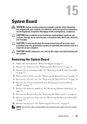
.... See "Removing the System-Board Shield" on page 31. 8 Remove the Mini-Card(s). See "Removing Memory Module(s)" on page 53. 7 Remove the memory module(s). For additional safety best practices information, see the Regulatory Compliance Homepage at dell.com/regulatory_compliance. See "Removing the Mini-Card(s)" on your computer. System Board 65 15 System Board...
.... See "Removing the System-Board Shield" on page 31. 8 Remove the Mini-Card(s). See "Removing Memory Module(s)" on page 53. 7 Remove the memory module(s). For additional safety best practices information, see the Regulatory Compliance Homepage at dell.com/regulatory_compliance. See "Removing the Mini-Card(s)" on your computer. System Board 65 15 System Board...
Owners Manual
Page 67
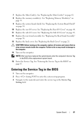
... Cover" on the computer, replace all screws and ensure that no stray screws remain inside the computer. CAUTION: Before turning on page 21. See "Replacing Memory Module(s)" on page 54. 10 Replace the rear I /O cover. See "Replacing the System-Board Shield" on page 33. 9 Replace the system-board shield.... Service Tag in damage to the computer. 14 Turn on page 67. See "Replacing the Rear-Stand Assembly" on page 63. 8 Replace the memory module(s). Failure to the main tab and enter the service tag in the BIOS" on the computer. See "Entering the Service Tag in the Service...
... Cover" on the computer, replace all screws and ensure that no stray screws remain inside the computer. CAUTION: Before turning on page 21. See "Replacing Memory Module(s)" on page 54. 10 Replace the rear I /O cover. See "Replacing the System-Board Shield" on page 33. 9 Replace the system-board shield.... Service Tag in damage to the computer. 14 Turn on page 67. See "Replacing the Rear-Stand Assembly" on page 63. 8 Replace the memory module(s). Failure to the main tab and enter the service tag in the BIOS" on the computer. See "Entering the Service Tag in the Service...
Owners Manual
Page 125
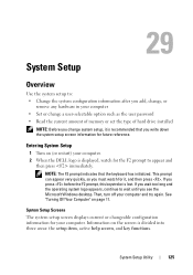
... current or changeable configuration information for future reference. System Setup Utility 125 See "Turning Off Your Computer" on (or restart) your computer. 2 When the DELL logo is recommended that the keyboard has initialized. Information on the screen is lost. If you press before the F2 prompt, this keystroke is divided...or remove any hardware in your computer • Set or change a user-selectable option such as the user password • Read the current amount of memory or set the type of hard drive installed NOTE: Before you change system setup, it , and then press .
... current or changeable configuration information for future reference. System Setup Utility 125 See "Turning Off Your Computer" on (or restart) your computer. 2 When the DELL logo is recommended that the keyboard has initialized. Information on the screen is lost. If you press before the F2 prompt, this keystroke is divided...or remove any hardware in your computer • Set or change a user-selectable option such as the user password • Read the current amount of memory or set the type of hard drive installed NOTE: Before you change system setup, it , and then press .
Owners Manual
Page 127
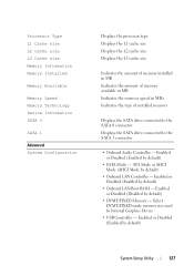
...by default) • Onboard LAN Boot ROM - Processor Type L1 Cache size L2 Cache size L3 Cache size Memory Information Memory Installed Memory Available Memory Speed Memory Technology Device Information SATA 0 SATA 1 Advanced System Configuration Displays the processor type Displays the L1 cache size Displays ... to the SATA 1 connector • Onboard Audio Controller - ATA Mode or AHCI Mode (AHCI Mode by default) • DVMT/FIXED Memory - Enabled or Disabled (Disabled by default) • Onboard LAN Controller - Enabled or Disabled (Enabled by Internal Graphics Device • USB...
...by default) • Onboard LAN Boot ROM - Processor Type L1 Cache size L2 Cache size L3 Cache size Memory Information Memory Installed Memory Available Memory Speed Memory Technology Device Information SATA 0 SATA 1 Advanced System Configuration Displays the processor type Displays the L1 cache size Displays ... to the SATA 1 connector • Onboard Audio Controller - ATA Mode or AHCI Mode (AHCI Mode by default) • DVMT/FIXED Memory - Enabled or Disabled (Disabled by default) • Onboard LAN Controller - Enabled or Disabled (Enabled by Internal Graphics Device • USB...
Owners Manual
Page 131
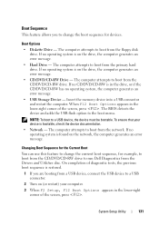
... sequence for example, to boot from the CD/DVD/CD-RW drive to boot from the Drivers and Utilities disc. The computer attempts to run Dell Diagnostics from the network. The computer attempts to change the current boot sequence, for devices. If no CD/DVD/CD-RW is restored. 1 If you... the floppy disk drive. The BIOS detects the device and adds the USB flash option to a USB device, the device must be bootable. Insert the memory device into a USB connector and restart the computer. System Setup Utility 131
... sequence for example, to boot from the CD/DVD/CD-RW drive to boot from the Drivers and Utilities disc. The computer attempts to run Dell Diagnostics from the network. The computer attempts to change the current boot sequence, for devices. If no CD/DVD/CD-RW is restored. 1 If you... the floppy disk drive. The BIOS detects the device and adds the USB flash option to a USB device, the device must be bootable. Insert the memory device into a USB connector and restart the computer. System Setup Utility 131
Owners Manual
Page 132
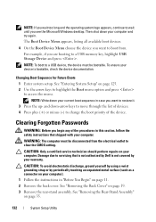
... a certified service technician should perform repairs on page 125. 2 Use the arrow keys to highlight the Boot menu option and press to a USB memory key, highlight USB Storage Device and press . The Boot Device Menu appears, listing all available boot devices. 4 On the Boot Device Menu choose ... Passwords WARNING: Before you begin any of the device. CAUTION: To avoid electrostatic discharge, ground yourself by using a wrist grounding strap or by Dell is bootable, check the device documentation. For example, if you are booting to access the menu. Damage due to restore it. 3 Press the...
... a certified service technician should perform repairs on page 125. 2 Use the arrow keys to highlight the Boot menu option and press to a USB memory key, highlight USB Storage Device and press . The Boot Device Menu appears, listing all available boot devices. 4 On the Boot Device Menu choose ... Passwords WARNING: Before you begin any of the device. CAUTION: To avoid electrostatic discharge, ground yourself by using a wrist grounding strap or by Dell is bootable, check the device documentation. For example, if you are booting to access the menu. Damage due to restore it. 3 Press the...


