
Owners Manual
Page 4
Replacing the Optical Drive 29 6 Memory Module(s 31 Removing Memory Module(s 31 Replacing Memory Module(s 33 7 Rear-Stand Assembly 35 Removing the Rear-Stand Assembly 35 Replacing the Rear-Stand Assembly 36 8 VESA Mount 37 Removing the VESA Mount 37 Replacing the VESA Mount 38 9 I/O Cover 39 Rear I/O Cover 39 Removing the Rear I/O Cover 39 Replacing the Rear I/O Cover 40 Side I/O Cover 41 Removing the Side I/O Cover 41 Replacing the Side I/O Cover 41 10 Audio Video Board (Optional 43 Removing the Audio Video (AV) Board 43 4 Contents
Replacing the Optical Drive 29 6 Memory Module(s 31 Removing Memory Module(s 31 Replacing Memory Module(s 33 7 Rear-Stand Assembly 35 Removing the Rear-Stand Assembly 35 Replacing the Rear-Stand Assembly 36 8 VESA Mount 37 Removing the VESA Mount 37 Replacing the VESA Mount 38 9 I/O Cover 39 Rear I/O Cover 39 Removing the Rear I/O Cover 39 Replacing the Rear I/O Cover 40 Side I/O Cover 41 Removing the Side I/O Cover 41 Replacing the Side I/O Cover 41 10 Audio Video Board (Optional 43 Removing the Audio Video (AV) Board 43 4 Contents
Owners Manual
Page 16
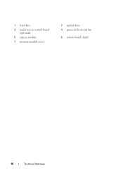
1 hard drive 3 touch-screen control board (optional) 5 camera module 7 memory-module cover 2 optical drive 4 processor heat-sink fan 6 system-board shield 16 Technical Overview
1 hard drive 3 touch-screen control board (optional) 5 camera module 7 memory-module cover 2 optical drive 4 processor heat-sink fan 6 system-board shield 16 Technical Overview
Owners Manual
Page 18
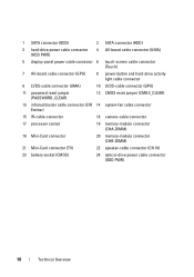
... cable connector (CIR 14 system-fan cable connector Emitter) 15 IR-cable connector 16 camera-cable connector 17 processor socket 18 memory-module connector (CHA-DIMM) 19 Mini-Card connector 20 memory-module connector (CHB-DIMM) 21 Mini-Card connector (TV) 22 speaker-cable connector (CN 10) 23 battery socket (CMOS) 24 optical-drive...
... cable connector (CIR 14 system-fan cable connector Emitter) 15 IR-cable connector 16 camera-cable connector 17 processor socket 18 memory-module connector (CHA-DIMM) 19 Mini-Card connector 20 memory-module connector (CHB-DIMM) 21 Mini-Card connector (TV) 22 speaker-cable connector (CN 10) 23 battery socket (CMOS) 24 optical-drive...
Owners Manual
Page 31
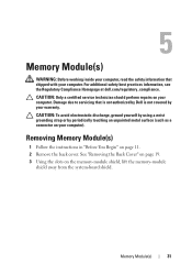
... by your warranty. Damage due to servicing that shipped with your computer. 5 Memory Module(s) WARNING: Before working inside your computer, read the safety information that is not authorized by Dell is not covered by periodically touching an unpainted metal surface (such as a connector... on your computer). Removing Memory Module(s) 1 Follow the instructions in "Before You Begin" on the memory-module shield, lift the memory-module shield away from the system-board...
... by your warranty. Damage due to servicing that shipped with your computer. 5 Memory Module(s) WARNING: Before working inside your computer, read the safety information that is not authorized by Dell is not covered by periodically touching an unpainted metal surface (such as a connector... on your computer). Removing Memory Module(s) 1 Follow the instructions in "Before You Begin" on the memory-module shield, lift the memory-module shield away from the system-board...
Owners Manual
Page 32
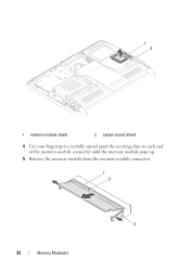
1 2 1 memory-module shield 2 system-board shield 4 Use your fingertips to carefully spread apart the securing clips on each end of the memory-module connector until the memory module pops up. 5 Remove the memory module from the memory-module connector. 1 2 3 32 Memory Module(s)
1 2 1 memory-module shield 2 system-board shield 4 Use your fingertips to carefully spread apart the securing clips on each end of the memory-module connector until the memory module pops up. 5 Remove the memory module from the memory-module connector. 1 2 3 32 Memory Module(s)
Owners Manual
Page 33
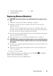
... screws remain inside the computer. If you do so may not boot. 1 Follow the instructions in the memorymodule connector. Check the amount of memory (RAM) listed. Control Memory Module(s) 33 1 memory-module connector 3 securing clips (2) 2 notch Replacing Memory Module(s) CAUTION: If the memory module is installed correctly, click Start PanelSystem and Security System.
... screws remain inside the computer. If you do so may not boot. 1 Follow the instructions in the memorymodule connector. Check the amount of memory (RAM) listed. Control Memory Module(s) 33 1 memory-module connector 3 securing clips (2) 2 notch Replacing Memory Module(s) CAUTION: If the memory module is installed correctly, click Start PanelSystem and Security System.

Owners Manual
Page 34
34 Memory Module(s)
34 Memory Module(s)
Owners Manual
Page 65
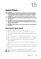
... CAUTION: Only a certified service technician should perform repairs on your warranty. See "Removing the Side I /O cover. See "Removing Memory Module(s)" on page 19. 3 Remove the rear-stand assembly. 15 System Board WARNING: Before working inside your computer, read the safety ...additional safety best practices information, see the Regulatory Compliance Homepage at dell.com/regulatory_compliance. See "Removing the System-Board Shield" on page 35. 4 Remove the rear I /O Cover" on page 83. See "Removing the Rear-Stand Assembly" on page 53. 7 Remove the memory module(s).
... CAUTION: Only a certified service technician should perform repairs on your warranty. See "Removing the Side I /O cover. See "Removing Memory Module(s)" on page 19. 3 Remove the rear-stand assembly. 15 System Board WARNING: Before working inside your computer, read the safety ...additional safety best practices information, see the Regulatory Compliance Homepage at dell.com/regulatory_compliance. See "Removing the System-Board Shield" on page 35. 4 Remove the rear I /O Cover" on page 83. See "Removing the Rear-Stand Assembly" on page 53. 7 Remove the memory module(s).
Owners Manual
Page 67
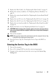
... replacement system board. 15 Enter the Service Tag. See "Replacing the System-Board Shield" on page 33. 9 Replace the system-board shield. See "Replacing Memory Module(s)" on page 54. 10 Replace the rear I /O Cover" on page 36. 13 Replace the back cover. See "Replacing the Back Cover" on page ...63. 8 Replace the memory module(s). See "Replacing the Mini-Card(s)" on page 21. 7 Replace the Mini-Card(s). Failure to the computer. 14 Turn on page 67. See "Entering the...
... replacement system board. 15 Enter the Service Tag. See "Replacing the System-Board Shield" on page 33. 9 Replace the system-board shield. See "Replacing Memory Module(s)" on page 54. 10 Replace the rear I /O Cover" on page 36. 13 Replace the back cover. See "Replacing the Back Cover" on page ...63. 8 Replace the memory module(s). See "Replacing the Mini-Card(s)" on page 21. 7 Replace the Mini-Card(s). Failure to the computer. 14 Turn on page 67. See "Entering the...


