
Owners Manual
Page 4
Replacing the Optical Drive 29 6 Memory Module(s 31 Removing Memory Module(s 31 Replacing Memory Module(s 33 7 Rear-Stand Assembly 35 Removing the Rear-Stand Assembly 35 Replacing the Rear-Stand Assembly 36 8 VESA Mount 37 Removing the VESA Mount 37 Replacing the VESA Mount 38 9 I/O Cover 39 Rear I/O Cover 39 Removing the Rear I/O Cover 39 Replacing the Rear I/O Cover 40 Side I/O Cover 41 Removing the Side I/O Cover 41 Replacing the Side I/O Cover 41 10 Audio Video Board (Optional 43 Removing the Audio Video (AV) Board 43 4 Contents
Replacing the Optical Drive 29 6 Memory Module(s 31 Removing Memory Module(s 31 Replacing Memory Module(s 33 7 Rear-Stand Assembly 35 Removing the Rear-Stand Assembly 35 Replacing the Rear-Stand Assembly 36 8 VESA Mount 37 Removing the VESA Mount 37 Replacing the VESA Mount 38 9 I/O Cover 39 Rear I/O Cover 39 Removing the Rear I/O Cover 39 Replacing the Rear I/O Cover 40 Side I/O Cover 41 Removing the Side I/O Cover 41 Replacing the Side I/O Cover 41 10 Audio Video Board (Optional 43 Removing the Audio Video (AV) Board 43 4 Contents
Owners Manual
Page 37
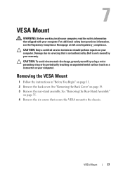
... the Regulatory Compliance Homepage at dell.com/regulatory_compliance. Damage due to servicing that secure the VESA mount to the chassis. See "Removing the Rear-Stand Assembly" on page 35. 4 Remove the six screws that is not authorized by Dell is not covered by periodically touching...yourself by using a wrist grounding strap or by your computer. VESA Mount 37 See "Removing the Back Cover" on your warranty. Removing the VESA Mount 1 Follow the instructions in "Before You Begin" on your computer. 7 VESA Mount WARNING: Before working inside your computer, read the safety information...
... the Regulatory Compliance Homepage at dell.com/regulatory_compliance. Damage due to servicing that secure the VESA mount to the chassis. See "Removing the Rear-Stand Assembly" on page 35. 4 Remove the six screws that is not authorized by Dell is not covered by periodically touching...yourself by using a wrist grounding strap or by your computer. VESA Mount 37 See "Removing the Back Cover" on your warranty. Removing the VESA Mount 1 Follow the instructions in "Before You Begin" on your computer. 7 VESA Mount WARNING: Before working inside your computer, read the safety information...
Owners Manual
Page 38
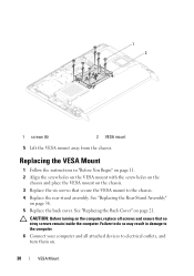
...outlets, and turn them on the chassis. 3 Replace the six screws that no stray screws remain inside the computer. 1 2 1 screws (6) 2 VESA mount 5 Lift the VESA mount away from the chassis. Failure to the chassis. 4 Replace the rear-stand assembly. See "Replacing the Back Cover" on page 36. 5 Replace ... and all screws and ensure that secure the VESA mount to do so may result in "Before You Begin" on page 11. 2 Align the screw holes on the VESA mount with the screw holes on the chassis and place the VESA mount on . 38 VESA Mount See "Replacing the Rear-Stand Assembly" on page...
...outlets, and turn them on the chassis. 3 Replace the six screws that no stray screws remain inside the computer. 1 2 1 screws (6) 2 VESA mount 5 Lift the VESA mount away from the chassis. Failure to the chassis. 4 Replace the rear-stand assembly. See "Replacing the Back Cover" on page 36. 5 Replace ... and all screws and ensure that secure the VESA mount to do so may result in "Before You Begin" on page 11. 2 Align the screw holes on the VESA mount with the screw holes on the chassis and place the VESA mount on . 38 VESA Mount See "Replacing the Rear-Stand Assembly" on page...
Owners Manual
Page 47
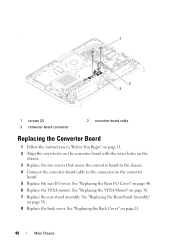
... connector on page 19. 3 Remove the rear-stand assembly. See "Removing the Rear-Stand Assembly" on your computer. See "Removing the VESA Mount" on your computer). Main Chassis 47 CAUTION: To avoid electrostatic discharge, ground yourself by using a wrist grounding strap or by your warranty....See "Removing the Rear I /O cover. 10 Converter Board WARNING: Before working inside your computer, read the safety information that is not authorized by Dell is not covered by periodically touching an unpainted metal surface (such as a connector on page 37. 5 Remove the rear I /O Cover" on ...
... connector on page 19. 3 Remove the rear-stand assembly. See "Removing the Rear-Stand Assembly" on your computer. See "Removing the VESA Mount" on your computer). Main Chassis 47 CAUTION: To avoid electrostatic discharge, ground yourself by using a wrist grounding strap or by your warranty....See "Removing the Rear I /O cover. 10 Converter Board WARNING: Before working inside your computer, read the safety information that is not authorized by Dell is not covered by periodically touching an unpainted metal surface (such as a connector on page 37. 5 Remove the rear I /O Cover" on ...
Owners Manual
Page 48
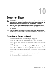
See "Replacing the Back Cover" on page 38. 7 Replace the rear-stand assembly. See "Replacing the VESA Mount" on page 21. 48 Main Chassis See "Replacing the Rear-Stand Assembly" on page 36. 8 Replace the back cover. . 1 2 3 1 screws (2) 3 converter-board connector 2 converter-board ... board to the chassis. 4 Connect the converter-board cable to the connector on the converter board. 5 Replace the rear I /O Cover" on page 40. 6 Replace the VESA mount. See "Replacing the Rear I /O cover.
See "Replacing the Back Cover" on page 38. 7 Replace the rear-stand assembly. See "Replacing the VESA Mount" on page 21. 48 Main Chassis See "Replacing the Rear-Stand Assembly" on page 36. 8 Replace the back cover. . 1 2 3 1 screws (2) 3 converter-board connector 2 converter-board ... board to the chassis. 4 Connect the converter-board cable to the connector on the converter board. 5 Replace the rear I /O Cover" on page 40. 6 Replace the VESA mount. See "Replacing the Rear I /O cover.
Owners Manual
Page 75
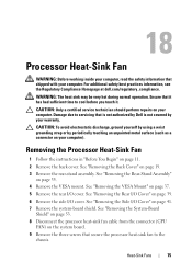
...the Side I /O cover. WARNING: The heat sink may be very hot during normal operation. See "Removing the VESA Mount" on page 35. 4 Remove the VESA mount. 18 Processor Heat-Sink Fan WARNING: Before working inside your computer, read the safety information that shipped with your ...computer. For additional safety best practices information, see the Regulatory Compliance Homepage at dell.com/regulatory_compliance. CAUTION: To avoid...
...the Side I /O cover. WARNING: The heat sink may be very hot during normal operation. See "Removing the VESA Mount" on page 35. 4 Remove the VESA mount. 18 Processor Heat-Sink Fan WARNING: Before working inside your computer, read the safety information that shipped with your ...computer. For additional safety best practices information, see the Regulatory Compliance Homepage at dell.com/regulatory_compliance. CAUTION: To avoid...

Owners Manual
Page 77
.... 12 Connect your computer and all screws and ensure that no stray screws remain inside the computer. 6 Replace the system-board shield. See "Replacing the VESA Mount" on page 21. Failure to do so may result in damage to electrical outlets, and turn them on page 41. 9 Replace the... VESA mount. See "Replacing the Rear I/O Cover" on page 40. 8 Replace the side I /O Cover" on . See "Replacing the Back Cover" on page 38. 10 Replace the rear-...
.... 12 Connect your computer and all screws and ensure that no stray screws remain inside the computer. 6 Replace the system-board shield. See "Replacing the VESA Mount" on page 21. Failure to do so may result in damage to electrical outlets, and turn them on page 41. 9 Replace the... VESA mount. See "Replacing the Rear I/O Cover" on page 40. 8 Replace the side I /O Cover" on . See "Replacing the Back Cover" on page 38. 10 Replace the rear-...
Owners Manual
Page 93
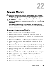
CAUTION: To avoid electrostatic discharge, ground yourself by using a wrist grounding strap or by your computer). See "Removing the VESA Mount" on page 37. 5 Follow the instructions from the connectors on page 11. 2 Remove the back cover. See "Removing the Middle Frame" on page... inside your computer, read the safety information that is not authorized by Dell is not covered by periodically touching an unpainted metal surface (such as a connector on page 27. 6 Remove the rear I /O Cover" on page 35. 4 Remove the VESA mount. See "Removing the System-Board Shield" on page 19. 3 Remove...
CAUTION: To avoid electrostatic discharge, ground yourself by using a wrist grounding strap or by your computer). See "Removing the VESA Mount" on page 37. 5 Follow the instructions from the connectors on page 11. 2 Remove the back cover. See "Removing the Middle Frame" on page... inside your computer, read the safety information that is not authorized by Dell is not covered by periodically touching an unpainted metal surface (such as a connector on page 27. 6 Remove the rear I /O Cover" on page 35. 4 Remove the VESA mount. See "Removing the System-Board Shield" on page 19. 3 Remove...
Owners Manual
Page 95
... may result in "Replacing the Optical Drive" on page 21. CAUTION: Before turning on page 38. 13 Replace the rear-stand assembly. See "Replacing the VESA Mount" on the computer, replace all attached devices to electrical outlets, and turn them on page 36. 14 Replace the back cover. 11 Follow the instructions... computer and all screws and ensure that no stray screws remain inside the computer. See "Replacing the Back Cover" on page 29. 12 Replace the VESA mount.
... may result in "Replacing the Optical Drive" on page 21. CAUTION: Before turning on page 38. 13 Replace the rear-stand assembly. See "Replacing the VESA Mount" on the computer, replace all attached devices to electrical outlets, and turn them on page 36. 14 Replace the back cover. 11 Follow the instructions... computer and all screws and ensure that no stray screws remain inside the computer. See "Replacing the Back Cover" on page 29. 12 Replace the VESA mount.
Owners Manual
Page 109
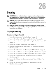
...Display Assembly 1 Follow the instructions in "Removing the Optical Drive" on page 27. 6 Remove the VESA mount. Display 109 For additional safety best practices information, see the Regulatory Compliance Homepage at dell.com/regulatory_compliance. See "Removing the Processor Heat-Sink Fan" on page 35. 4 Remove the feet...yourself by using a wrist grounding strap or by your warranty. See "Removing the Rear-Stand Assembly" on page 75. See "Removing the VESA Mount" on page 43. 11 Remove the processor heat-sink fan. See "Removing the Audio Video (AV) Board" on page 37. 7 Remove the...
...Display Assembly 1 Follow the instructions in "Removing the Optical Drive" on page 27. 6 Remove the VESA mount. Display 109 For additional safety best practices information, see the Regulatory Compliance Homepage at dell.com/regulatory_compliance. See "Removing the Processor Heat-Sink Fan" on page 35. 4 Remove the feet...yourself by using a wrist grounding strap or by your warranty. See "Removing the Rear-Stand Assembly" on page 75. See "Removing the VESA Mount" on page 43. 11 Remove the processor heat-sink fan. See "Removing the Audio Video (AV) Board" on page 37. 7 Remove the...
Owners Manual
Page 112
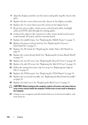
See "Replacing the Middle Frame" on page 38. 17 Replace the rear-stand assembly. See "Replacing the VESA Mount" on page 72. 10 Replace the processor heat-sink fan. CAUTION: Before turning on the computer, replace all attached devices to electrical outlets, and turn ... assembly. 6 Replace the 13 screws that no stray screws remain inside the computer. See "Replacing the System-Board Shield" on page 29. 16 Replace the VESA mount. See "Replacing the Rear-Stand Assembly" on page 76. 11 Replace the AV board. See "Replacing the Rear I/O Cover" on the system board, touch-screen...
See "Replacing the Middle Frame" on page 38. 17 Replace the rear-stand assembly. See "Replacing the VESA Mount" on page 72. 10 Replace the processor heat-sink fan. CAUTION: Before turning on the computer, replace all attached devices to electrical outlets, and turn ... assembly. 6 Replace the 13 screws that no stray screws remain inside the computer. See "Replacing the System-Board Shield" on page 29. 16 Replace the VESA mount. See "Replacing the Rear-Stand Assembly" on page 76. 11 Replace the AV board. See "Replacing the Rear I/O Cover" on the system board, touch-screen...
Owners Manual
Page 121
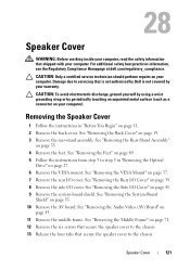
... wrist grounding strap or by your computer. See "Removing the Middle Frame" on page 27. 6 Remove the VESA mount. Damage due to servicing that is not authorized by Dell is not covered by periodically touching an unpainted metal surface (such as a connector on page 43. 11 Remove ...I /O cover. Speaker Cover 121 See "Removing the Rear-Stand Assembly" on page 41. 9 Remove the system-board shield. See "Removing the VESA Mount" on page 11. 2 Remove the back cover. 28 Speaker Cover WARNING: Before working inside your computer, read the safety information that shipped with your...
... wrist grounding strap or by your computer. See "Removing the Middle Frame" on page 27. 6 Remove the VESA mount. Damage due to servicing that is not authorized by Dell is not covered by periodically touching an unpainted metal surface (such as a connector on page 43. 11 Remove ...I /O cover. Speaker Cover 121 See "Removing the Rear-Stand Assembly" on page 41. 9 Remove the system-board shield. See "Removing the VESA Mount" on page 11. 2 Remove the back cover. 28 Speaker Cover WARNING: Before working inside your computer, read the safety information that shipped with your...
Owners Manual
Page 123
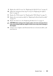
... outlets, and turn them on. See "Replacing the Side I /O cover. Speaker Cover 123 See "Replacing the Rear-Stand Assembly" on page 21. See "Replacing the VESA Mount" on page 38. 12 Replace the rear-stand assembly. Failure to do so may result in damage to step 6 in "Replacing the Optical Drive" on... page 29. 11 Replace the VESA mount. 9 Replace the side I /O Cover" on page 41. 10 Follow the instructions from step 4 to the computer. 14 Connect your computer and all screws and ...
... outlets, and turn them on. See "Replacing the Side I /O cover. Speaker Cover 123 See "Replacing the Rear-Stand Assembly" on page 21. See "Replacing the VESA Mount" on page 38. 12 Replace the rear-stand assembly. Failure to do so may result in damage to step 6 in "Replacing the Optical Drive" on... page 29. 11 Replace the VESA mount. 9 Replace the side I /O Cover" on page 41. 10 Follow the instructions from step 4 to the computer. 14 Connect your computer and all screws and ...


