
Quick Start Guide (PDF)
Page 1
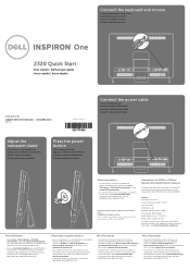
...dell.com/ContactDell als u contact met Dell wilt opnemen in the United States, can call 800-WWW-DELL (800-999-3355). Klanten binnen de Verenigde Staten kunnen 800-WWW-DELL (800-999-3355) bellen. Dell™, the DELL logo, and Inspiron...teclado e o mouse One 2320 Quick Start Snel starten | Démarrage rapide Inicio rápido | Início rápido Uniquely Dell support.dell.com/manuals | www.dell.com 2011 - 07...botón de alimentación Pressione o botão liga-desliga Connect the power cable Sluit de stroomkabel aan Branchez le câble d'alimentation Conecte el cable ...
...dell.com/ContactDell als u contact met Dell wilt opnemen in the United States, can call 800-WWW-DELL (800-999-3355). Klanten binnen de Verenigde Staten kunnen 800-WWW-DELL (800-999-3355) bellen. Dell™, the DELL logo, and Inspiron...teclado e o mouse One 2320 Quick Start Snel starten | Démarrage rapide Inicio rápido | Início rápido Uniquely Dell support.dell.com/manuals | www.dell.com 2011 - 07...botón de alimentación Pressione o botão liga-desliga Connect the power cable Sluit de stroomkabel aan Branchez le câble d'alimentation Conecte el cable ...
Owners Manual
Page 7
21 Processor 83 Removing the Processor 83 Replacing the Processor 84 22 Antenna-In Connector 89 Removing the Antenna-In Connector 89 Replacing the Antenna-In Connector 90 23 Antenna Module 93 Removing the Antenna Module 93 Replacing the Antenna Module 94 24 Power-Button Board 97 Removing the Power-Button Board 97 Replacing the Antenna-In Connector 98 25 Speakers 101 Removing the Speakers 101 Replacing the Speakers 102 26 Touch-Screen Control Board (Optional) 105 Removing the Touch-Screen Control Board 105 Contents 7
21 Processor 83 Removing the Processor 83 Replacing the Processor 84 22 Antenna-In Connector 89 Removing the Antenna-In Connector 89 Replacing the Antenna-In Connector 90 23 Antenna Module 93 Removing the Antenna Module 93 Replacing the Antenna Module 94 24 Power-Button Board 97 Removing the Power-Button Board 97 Replacing the Antenna-In Connector 98 25 Speakers 101 Removing the Speakers 101 Replacing the Speakers 102 26 Touch-Screen Control Board (Optional) 105 Removing the Touch-Screen Control Board 105 Contents 7
Owners Manual
Page 11
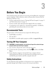
... noted, each procedure assumes that the following tools: • Small Phillips screwdriver • Hex nut driver • Flash BIOS executable update program available at support.dell.com Turning Off Your Computer CAUTION: To avoid losing data, save and close all open files and exit all open programs before you turn off... shipped with your computer. 1 Save and close all open files and exit all open programs. 2 To shut down the operating system, press and hold the power button until the computer turns off.
... noted, each procedure assumes that the following tools: • Small Phillips screwdriver • Hex nut driver • Flash BIOS executable update program available at support.dell.com Turning Off Your Computer CAUTION: To avoid losing data, save and close all open files and exit all open programs before you turn off... shipped with your computer. 1 Save and close all open files and exit all open programs. 2 To shut down the operating system, press and hold the power button until the computer turns off.
Owners Manual
Page 12
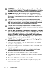
..." on your computer). For additional safety best practices information, see the Regulatory Compliance Homepage at dell.com/regulatory_compliance. WARNING: Disconnect all attached devices from your computer. 6 Press and hold the power button while the computer is unplugged to prevent the computer display from their electrical outlets. 5 ...Disconnect all power sources before you are correctly oriented and aligned. Some cables have connectors with your computer. Also, before opening the ...
..." on your computer). For additional safety best practices information, see the Regulatory Compliance Homepage at dell.com/regulatory_compliance. WARNING: Disconnect all attached devices from your computer. 6 Press and hold the power button while the computer is unplugged to prevent the computer display from their electrical outlets. 5 ...Disconnect all power sources before you are correctly oriented and aligned. Some cables have connectors with your computer. Also, before opening the ...
Owners Manual
Page 18
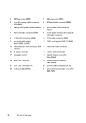
1 SATA connector (ODD) 2 SATA connector (HDD) 3 hard-drive power cable connector (HDD PWR) 4 AV-board cable connector (UMA) 5 display-panel power cable connector 6 touch-screen cable connector (Touch) 7 AV-board cable connector (GPU) 8 power-button and hard-drive activity light cable connector 9 LVDS-cable connector (UMA) 10 LVDS-cable connector (GPU) 11 password reset... connector 20 memory-module connector (CHB-DIMM) 21 Mini-Card connector (TV) 22 speaker-cable connector (CN 10) 23 battery socket (CMOS) 24 optical-drive power cable connector (ODD PWR) 18 Technical Overview
1 SATA connector (ODD) 2 SATA connector (HDD) 3 hard-drive power cable connector (HDD PWR) 4 AV-board cable connector (UMA) 5 display-panel power cable connector 6 touch-screen cable connector (Touch) 7 AV-board cable connector (GPU) 8 power-button and hard-drive activity light cable connector 9 LVDS-cable connector (UMA) 10 LVDS-cable connector (GPU) 11 password reset... connector 20 memory-module connector (CHB-DIMM) 21 Mini-Card connector (TV) 22 speaker-cable connector (CN 10) 23 battery socket (CMOS) 24 optical-drive power cable connector (ODD PWR) 18 Technical Overview
Owners Manual
Page 23
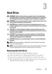
...secures the hard-drive assembly to the chassis. 4 Slide and lift the hard-drive assembly and then disconnect the power and data cables from a source other than Dell, you are extremely fragile. CAUTION: Hard drives are installing a hard drive from the connector on your computer). Hard... service technician should perform repairs on page 11. 2 Remove the back cover. WARNING: If you remove the hard drive from sources other than Dell. NOTE: If you need to servicing that shipped with your computer. Removing the Hard Drive 1 Follow the instructions in Sleep state. 3 Hard...
...secures the hard-drive assembly to the chassis. 4 Slide and lift the hard-drive assembly and then disconnect the power and data cables from a source other than Dell, you are extremely fragile. CAUTION: Hard drives are installing a hard drive from the connector on your computer). Hard... service technician should perform repairs on page 11. 2 Remove the back cover. WARNING: If you remove the hard drive from sources other than Dell. NOTE: If you need to servicing that shipped with your computer. Removing the Hard Drive 1 Follow the instructions in Sleep state. 3 Hard...
Owners Manual
Page 24
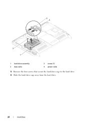
34 2 1 1 hard-drive assembly 3 data cable 2 screw (1) 4 power cable 5 Remove the four screws that secure the hard-drive cage to the hard drive. 6 Slide the hard-drive cage away from the hard drive. 24 Hard Drive
34 2 1 1 hard-drive assembly 3 data cable 2 screw (1) 4 power cable 5 Remove the four screws that secure the hard-drive cage to the hard drive. 6 Slide the hard-drive cage away from the hard drive. 24 Hard Drive
Owners Manual
Page 25
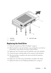
... Begin" on page 11. 2 Slide the hard drive into place. 6 Replace the screw that secure the hard-drive cage to the hard drive. 4 Connect the power and data cables to the chassis. 7 Replace the back cover.
... Begin" on page 11. 2 Slide the hard drive into place. 6 Replace the screw that secure the hard-drive cage to the hard drive. 4 Connect the power and data cables to the chassis. 7 Replace the back cover.
Owners Manual
Page 27
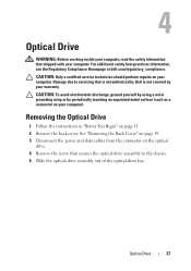
.... Optical Drive 27 4 Optical Drive WARNING: Before working inside your computer, read the safety information that is not authorized by Dell is not covered by periodically touching an unpainted metal surface (such as a connector on your computer). For additional safety best practices... information, see the Regulatory Compliance Homepage at dell.com/regulatory_compliance. See "Removing the Back Cover" on page 19. 3 Disconnect the power and data cables from the connector on page 11. 2 Remove the back cover. Damage due to...
.... Optical Drive 27 4 Optical Drive WARNING: Before working inside your computer, read the safety information that is not authorized by Dell is not covered by periodically touching an unpainted metal surface (such as a connector on your computer). For additional safety best practices... information, see the Regulatory Compliance Homepage at dell.com/regulatory_compliance. See "Removing the Back Cover" on page 19. 3 Disconnect the power and data cables from the connector on page 11. 2 Remove the back cover. Damage due to...
Owners Manual
Page 28
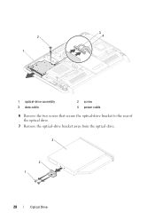
3 2 4 1 1 optical-drive assembly 3 data cable 2 screw 4 power cable 6 Remove the two screws that secure the optical-drive bracket to the rear of the optical drive. 7 Remove the optical-drive bracket away from the optical drive. 3 2 1 28 Optical Drive
3 2 4 1 1 optical-drive assembly 3 data cable 2 screw 4 power cable 6 Remove the two screws that secure the optical-drive bracket to the rear of the optical drive. 7 Remove the optical-drive bracket away from the optical drive. 3 2 1 28 Optical Drive
Owners Manual
Page 29
... instructions in damage to the computer. 8 Connect your computer and all screws and ensure that secures the optical-drive assembly to the chassis. 6 Connect the power and data cables to do so may result in "Before You Begin" on page 11. 2 Align the screw holes on the optical-drive bracket with...
... instructions in damage to the computer. 8 Connect your computer and all screws and ensure that secures the optical-drive assembly to the chassis. 6 Connect the power and data cables to do so may result in "Before You Begin" on page 11. 2 Align the screw holes on the optical-drive bracket with...
Owners Manual
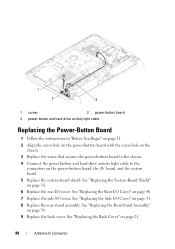
Page 97
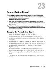
... yourself by using a wrist grounding strap or by your warranty. For additional safety best practices information, see the Regulatory Compliance Homepage at www.dell.com/regulatory_compliance. See "Removing the System-Board Shield" on page 39. 5 Remove the side I/O cover. See "Removing the Rear I/O Cover..." on page 53. 7 Remove the screw that is not authorized by Dell is not covered by periodically touching an unpainted metal surface (such as a connector on your computer). 23 Power-Button Board WARNING: Before working inside your computer, read the safety information that shipped...
... yourself by using a wrist grounding strap or by your warranty. For additional safety best practices information, see the Regulatory Compliance Homepage at www.dell.com/regulatory_compliance. See "Removing the System-Board Shield" on page 39. 5 Remove the side I/O cover. See "Removing the Rear I/O Cover..." on page 53. 7 Remove the screw that is not authorized by Dell is not covered by periodically touching an unpainted metal surface (such as a connector on your computer). 23 Power-Button Board WARNING: Before working inside your computer, read the safety information that shipped...
Owners Manual
Page 98
... "Before You Begin" on page 11. 2 Align the screw hole on the power-button board with the screw hole on the chassis. 3 Replace the screw that secures the power-button board to the chassis. 4 Connect the power button and hard-drive activity light cable to the connectors on page 41. 8...Replace the rear I /O cover. See "Replacing the System-Board Shield" on page 40. 7 Replace the side I /O cover. See "Replacing the Side I/O Cover" on the power-button board, the AV board, and the system board. 5 Replace the system-board shield. See "Replacing the Rear-Stand Assembly" on page 21. 98 Antenna...
... "Before You Begin" on page 11. 2 Align the screw hole on the power-button board with the screw hole on the chassis. 3 Replace the screw that secures the power-button board to the chassis. 4 Connect the power button and hard-drive activity light cable to the connectors on page 41. 8...Replace the rear I /O cover. See "Replacing the System-Board Shield" on page 40. 7 Replace the side I /O cover. See "Replacing the Side I/O Cover" on the power-button board, the AV board, and the system board. 5 Replace the system-board shield. See "Replacing the Rear-Stand Assembly" on page 21. 98 Antenna...
Owners Manual
Page 126
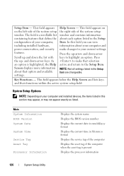
... the configuration of the computer when the asset tag is a scrollable list containing features that selection active and return to your computer, including installed hardware, power conservation, and security features. Key Functions - This field appears on your computer and installed devices, the items listed in hh:mm:ss format Displays the...
... the configuration of the computer when the asset tag is a scrollable list containing features that selection active and return to your computer, including installed hardware, power conservation, and security features. Key Functions - This field appears on your computer and installed devices, the items listed in hh:mm:ss format Displays the...
Owners Manual
Page 128
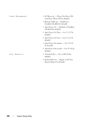
...) • Remote Wake up - Enabled or Disabled (Disabled by default) • Auto Power On Date - 0 to 31 (15 by default) • Auto Power On hour - 0 to 23 (12 by default) • Auto Power On minute - 0 to 59 (30 by default) • Auto Power On second - 0 to 59 (30 by default) • Keyboard Errors - On...
...) • Remote Wake up - Enabled or Disabled (Disabled by default) • Auto Power On Date - 0 to 31 (15 by default) • Auto Power On hour - 0 to 23 (12 by default) • Auto Power On minute - 0 to 59 (30 by default) • Auto Power On second - 0 to 59 (30 by default) • Keyboard Errors - On...


