
Dell Inspiron One 2320 Support Question
Dell Inspiron One 2320 Support Question
Find answers below for this question about Dell Inspiron One 2320.Need a Dell Inspiron One 2320 manual? We have 3 online manuals for this item!
Question posted by Shellej153 on May 16th, 2013
My Daughters 2320 Needs The Part Where The Power Cord Plugs In. She Unplugged Th
She unplugged the power cord and the part broke. She can't plug the power cord back in. What's the name of that part and the number for it. Is it easy to replace.
Current Answers
Answer #1: Posted by prateekk007 on May 18th, 2013 10:35 PM
prateekk007

Member since:
December 5th, 2012 Points: 2,137,520

Member since:
December 5th, 2012 Points: 2,137,520
Hi Shellej153
In case adaptor port is broken then whole motherboard needs to be replaced. Motherboard is not a customer replaceable unit; you need to take help from a specialist. In case your system is under warranty please provide me the system service tag or the express service code on Twitter (@PrateekAtDell). You can follow/DM me your system's service tag. I'll be glad to help. Please click on the link mentioned below to check the warranty status.
Please reply if you have any further questions.
For easy access to drivers, manuals and product updates, please visit our Support Site .Thanks & Regards
Prateek K
Related Dell Inspiron One 2320 Manual Pages
Quick Start Guide (PDF) - Page 1
... en geavanceerde opties die voor uw desktop beschikbaar zijn.
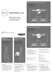
• Ga naar... Conecte o teclado e o mouse
One
2320 Quick Start
Snel starten | Démarrage...botão liga-desliga
Connect the power cable
Sluit de stroomkabel aan Branchez ...™, the DELL logo, and Inspiron™ are trademarks of problemen voor...(800-999-3355) bellen.
Regulatory Model Number: W03C Input Voltage: 100-240 VAC ...
Owners Manual - Page 2
.... Reproduction of these materials in this document is strictly forbidden. Other trademarks and trade names may be used in this document to refer to hardware or loss of Dell Inc.... in this text: Dell™, the DELL™ logo, and Inspiron™ are either the entities claiming the marks and names or their products. Dell Inc.
WARNING: A WARNING indicates a potential...
Owners Manual - Page 3
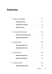
... Computer 11 Safety Instructions 11
2 Technical Overview 15
Inside View of Your Inspiron One 15 System Board Components 17
3 Back Cover 19
Removing the Back Cover 19 Replacing the Back Cover 21
4 Hard Drive 23
Removing the Hard Drive 23 Replacing the Hard Drive 25
5 Optical Drive 27
Removing the Optical Drive 27...
Owners Manual - Page 4
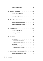
... Rear-Stand Assembly 36
8 VESA Mount 37
Removing the VESA Mount 37 Replacing the VESA Mount 38
9 I/O Cover 39
Rear I/O Cover 39 Removing the Rear I/O Cover 39 Replacing the Rear I/O Cover 40
Side I/O Cover 41 Removing the Side I/O Cover 41 Replacing the Side I/O Cover 41
10 Audio Video Board (Optional 43
Removing the...
Owners Manual - Page 7
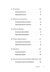
... Antenna-In Connector 90
23 Antenna Module 93
Removing the Antenna Module 93 Replacing the Antenna Module 94
24 Power-Button Board 97
Removing the Power-Button Board 97 Replacing the Antenna-In Connector 98
25 Speakers 101
Removing the Speakers 101 Replacing the Speakers 102
26 Touch-Screen Control Board (Optional) 105
Removing the...
Owners Manual - Page 11
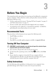
... protect your computer from potential damage and to help to ensure your computer. • A component can be replaced or-if purchased separately-installed by
performing the removal procedure in reverse order.
Safety Instructions
Use the following conditions ...open programs.
2 To shut down the operating system, press and hold the power button until the computer turns off your computer.
Owners Manual - Page 12
...aligned to the power source.
See "Turning Off Your Computer" on the cable itself.
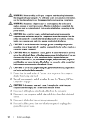
CAUTION: To disconnect a network cable, first unplug the cable from your computer and then unplug the cable ... the computer cover and access any connector pins. After the installation is authorized to replace, remove, or install accessories. CAUTION: To avoid damaging the computer, perform the following...
Owners Manual - Page 18
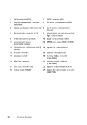
1 SATA connector (ODD)
2 SATA connector (HDD)
3 hard-drive power cable connector (HDD PWR)
4 AV-board cable connector (UMA)
5 display-panel power cable connector 6 touch-screen cable connector (Touch)
7 AV-board cable connector (GPU)
8 power-button and hard-drive activity light cable connector
9 LVDS-cable connector (UMA)
10 LVDS-cable connector (GPU)
11 password reset...
Owners Manual - Page 23
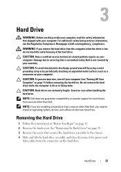
Exercise care when handling the hard drive. WARNING: If you need to the chassis. 4 Slide and lift the hard-drive assembly and then disconnect the power and
data cables from the connector on the new hard drive. CAUTION: To prevent data loss, turn off your computer (see the Regulatory Compliance Homepage ...
Owners Manual - Page 24
34
2 1
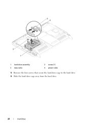
1 hard-drive assembly 3 data cable
2 screw (1) 4 power cable
5 Remove the four screws that secure the hard-drive cage to the hard drive. 6 Slide the hard-drive cage away from the hard drive.
24
Hard Drive
Owners Manual - Page 25
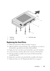
... the connector on the hard drive. 5 Place the hard-drive assembly on page 21. See "Replacing the Back Cover" on the chassis and slide the hard-drive
assembly into the hard-drive cage,... the screw holes on the hard drive. 3 Replace the four screws that secure the hard-drive cage to the hard drive. 4 Connect the power and data cables to the chassis. 7 Replace the back cover.
Hard Drive
25
Owners Manual - Page 27
...
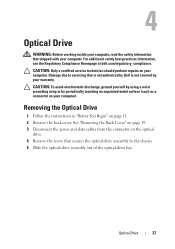
WARNING: Before working inside your computer, read the safety information that shipped with your warranty.
See "Removing the Back Cover" on page 19. 3 Disconnect the power and data cables from the connector on page 11. 2 Remove the back cover. For additional safety best practices information, see the Regulatory Compliance Homepage at...
Owners Manual - Page 28
3
2
4
1
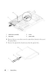
1 optical-drive assembly 3 data cable
2 screw 4 power cable
6 Remove the two screws that secure the optical-drive bracket to the rear of the optical drive.
7 Remove the optical-drive bracket away from the optical drive.
3
2 1
28
Optical Drive
Owners Manual - Page 29
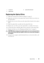
.... 8 Connect your computer and all screws and ensure that secures the optical-drive assembly to the chassis. 6 Connect the power and data cables to the connector on the optical drive. 7 Replace the back cover. CAUTION: Before turning on the computer, replace all attached devices to electrical outlets, and turn them on page 21.
Owners Manual - Page 97
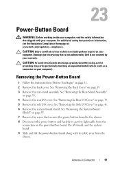
... "Removing the System-Board
Shield" on page 53. 7 Remove the screw that secures the power-button board to servicing that is not authorized by Dell is not covered by periodically touching an... (such as a connector on your computer).
Damage due to the chassis. 8 Disconnect the power button and hard-drive activity light cable from the chassis. CAUTION: Only a certified service technician...
Owners Manual - Page 98
... Assembly" on page 21.
98
Antenna-In Connector See "Replacing the Side I /O cover. 1
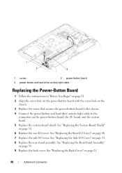
2
3
1 screw
2 power-button board
3 power-button and hard-drive activity light cable
Replacing the Power-Button Board
1 Follow the instructions in "Before You Begin" on page 11. 2 Align the screw hole on the power-button board with the screw hole on the
chassis...
Owners Manual - Page 126
... Date
System Time
Service Tag Asset Tag
Processor Information
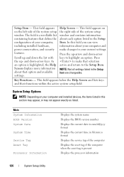
Displays the system name Displays the BIOS version number Displays the current date in mm/dd/yyyy format Displays the current time...
System Setup Utility System Setup Options
NOTE: Depending on your computer, including installed hardware, power conservation, and security features. NOTE: Not all settings listed in this field you can ...
Owners Manual - Page 128
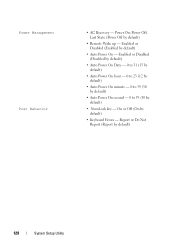
... Utility Report or Do Not Report (Report by default)
• Remote Wake up - Power Off; On or Off (On by default)
• Auto Power On - Enabled or Disabled (Enabled by default)
• Keyboard Errors - Power On; Enabled or Disabled (Disabled by default)
• Auto Power On Date - 0 to 31 (15 by default)
• Auto...
Owners Manual - Page 133

... on pins 2
and 3. See "System Board Components" on page 17. 8 Remove the 2-pin jumper plug from pins 2 and 3 and fix it on pins 1 and 2.
9 Wait for approximately five seconds to clear... the password setting. 10 Remove the 2-pin jumper plug from pins 1 and 2 and replace it on page 39. 5 Remove the side I/O cover. See "Removing the System-Board
Shield...
Owners Manual - Page 135
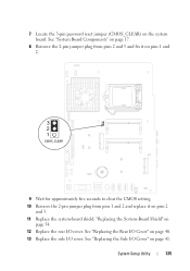
... CMOS setting. 10 Remove the 2-pin jumper plug from pins 1 and 2 and replace it on page 41.
"Replacing the System-Board Shield" on
page 54. 12 Replace the rear I /O cover. See "Replacing the Rear I/O Cover" on the system board. See "Replacing the Side I/O Cover" on pins 2
and 3. 11 Replace the system-board shield. System Setup Utility
135...
Similar Questions

Desktop Inspiron 1 2320 Black Screen When Restarting
(Posted by tmiskkevi 10 years ago)

I Have A Dell Optiplex 330 And Need Cables To Plug In Monitor And Also Power
cable where can i get them
cable where can i get them
(Posted by mnchihafe 10 years ago)


How To Bypass A Bios Password On Dell Desktop Inspiron One 2320
(Posted by bexoxo 10 years ago)