
Owners Manual
Page 8
... the Camera Module 117 Replacing the Camera Module 118 29 Speaker Cover 121 Removing the Speaker Cover 121 Replacing the Speaker Cover 122 30 System Setup 125 Overview 125 Entering System Setup 125 System Setup Options 126 8 Contents
... the Camera Module 117 Replacing the Camera Module 118 29 Speaker Cover 121 Removing the Speaker Cover 121 Replacing the Speaker Cover 122 30 System Setup 125 Overview 125 Entering System Setup 125 System Setup Options 126 8 Contents
Owners Manual
Page 57
... I /O Cover" on page 41. 6 Remove the system-board shield. For additional safety best practices information, see the Regulatory Compliance Homepage at dell.com/regulatory_compliance. CAUTION: To avoid electrostatic discharge, ground yourself by using a wrist grounding strap or by the manufacturer. See "Removing the Side I...in "Before You Begin" on page 17. See "Removing the Back Cover" on page 125. 2 Remove the back cover. See "System Setup" on page 19. 3 Remove the rear-stand assembly. See "Removing the System-Board Shield" on your computer. Damage due to the manufacturer's...
... I /O Cover" on page 41. 6 Remove the system-board shield. For additional safety best practices information, see the Regulatory Compliance Homepage at dell.com/regulatory_compliance. CAUTION: To avoid electrostatic discharge, ground yourself by using a wrist grounding strap or by the manufacturer. See "Removing the Side I...in "Before You Begin" on page 17. See "Removing the Back Cover" on page 125. 2 Remove the back cover. See "System Setup" on page 19. 3 Remove the rear-stand assembly. See "Removing the System-Board Shield" on your computer. Damage due to the manufacturer's...
Owners Manual
Page 59
... "Replacing the Rear-Stand Assembly" on page 41. 6 Replace the rear-stand assembly. Failure to do so may result in step 1. See "System Setup" on . 9 Enter the system setup and restore the settings you recorded in damage to the computer. 8 Connect your computer and devices to electrical outlets, and then turn them...
... "Replacing the Rear-Stand Assembly" on page 41. 6 Replace the rear-stand assembly. Failure to do so may result in step 1. See "System Setup" on . 9 Enter the system setup and restore the settings you recorded in damage to the computer. 8 Connect your computer and devices to electrical outlets, and then turn them...
Owners Manual
Page 67
... in damage to the main tab and enter the service tag in the BIOS 1 Turn on the computer. 2 Press during POST to enter the system setup program. 3 Navigate to the computer. 14 Turn on page 67. 7 Replace the Mini-Card(s).
... in damage to the main tab and enter the service tag in the BIOS 1 Turn on the computer. 2 Press during POST to enter the system setup program. 3 Navigate to the computer. 14 Turn on page 67. 7 Replace the Mini-Card(s).
Owners Manual
Page 125
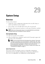
...quickly, so you press before the F2 prompt, this keystroke is divided into three areas: the setup item, active help screen, and key functions. System Setup Screens The system setup screen displays current or changeable configuration information for the F2 prompt to appear and then press immediately.... the current amount of memory or set the type of hard drive installed NOTE: Before you change system setup, it , and then press . Entering System Setup 1 Turn on (or restart) your computer. 2 When the DELL logo is recommended that the keyboard has initialized. Information on page 11.
...quickly, so you press before the F2 prompt, this keystroke is divided into three areas: the setup item, active help screen, and key functions. System Setup Screens The system setup screen displays current or changeable configuration information for the F2 prompt to appear and then press immediately.... the current amount of memory or set the type of hard drive installed NOTE: Before you change system setup, it , and then press . Entering System Setup 1 Turn on (or restart) your computer. 2 When the DELL logo is recommended that the keyboard has initialized. Information on page 11.
Owners Manual
Page 126
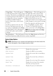
... field appears below the Help Screen and lists keys and their functions within the active system setup field. Setup Item - and down the list with the up -arrow and down-arrow keys to the Setup Item. This field appears on your computer, including installed hardware, power conservation, and security ... name Displays the BIOS version number Displays the current date in mm/dd/yyyy format Displays the current time in the Setup Item. Press the up - System Setup Options NOTE: Depending on the right side of the computer when the asset tag is highlighted, the Help Screen displays ...
... field appears below the Help Screen and lists keys and their functions within the active system setup field. Setup Item - and down the list with the up -arrow and down-arrow keys to the Setup Item. This field appears on your computer, including installed hardware, power conservation, and security ... name Displays the BIOS version number Displays the current date in mm/dd/yyyy format Displays the current time in the Setup Item. Press the up - System Setup Options NOTE: Depending on the right side of the computer when the asset tag is highlighted, the Help Screen displays ...
Owners Manual
Page 127
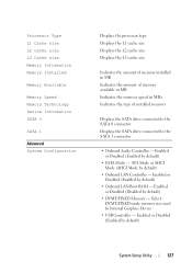
... Disabled (Disabled by default) • Onboard LAN Boot ROM - Enabled or Disabled (Enabled by default) • SATA Mode - Enabled or Disabled (Enabled by default) System Setup Utility 127 Select DVMT/FIXED mode memory size used by default) • Onboard LAN Controller - ATA Mode or AHCI Mode (AHCI Mode by Internal Graphics...
... Disabled (Disabled by default) • Onboard LAN Boot ROM - Enabled or Disabled (Enabled by default) • SATA Mode - Enabled or Disabled (Enabled by default) System Setup Utility 127 Select DVMT/FIXED mode memory size used by default) • Onboard LAN Controller - ATA Mode or AHCI Mode (AHCI Mode by Internal Graphics...
Owners Manual
Page 128
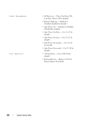
... (12 by default) • Auto Power On minute - 0 to 59 (30 by default) • Auto Power On second - 0 to 59 (30 by default) 128 System Setup Utility On or Off (On by default) • Remote Wake up - Last State (Power Off by default) • Keyboard Errors - Power On; Power Off; Enabled...
... (12 by default) • Auto Power On minute - 0 to 59 (30 by default) • Auto Power On second - 0 to 59 (30 by default) 128 System Setup Utility On or Off (On by default) • Remote Wake up - Last State (Power Off by default) • Keyboard Errors - Power On; Power Off; Enabled...

Owners Manual
Page 129
... to enable in each processor package • Limit CPUID Value - Enabled or Disabled (Enabled by default) • Multi Core Support - All; 1; 2; 3; (All by default) System Setup Utility 129 When enabled, VMM utilizes the additional hardware capabilities provided by default). Enabled or Disabled (Enabled by Vanderpool Technology. • Intel(R) SpeedStep - This field...
... to enable in each processor package • Limit CPUID Value - Enabled or Disabled (Enabled by default) • Multi Core Support - All; 1; 2; 3; (All by default) System Setup Utility 129 When enabled, VMM utilizes the additional hardware capabilities provided by default). Enabled or Disabled (Enabled by Vanderpool Technology. • Intel(R) SpeedStep - This field...

Owners Manual
Page 130
...; Hard Drive; HDD protection Boot 1st Boot Priority 2nd Boot Priority 3rd Boot Priority 4th Boot Priority 5th Boot Priority Exit Exit Options 130 System Setup Utility Enabled or Disabled (Disabled by default) Specifies the boot sequence from the available devices Diskette Drive; Disabled (Diskette Drive by default) Specifies the boot...
...; Hard Drive; HDD protection Boot 1st Boot Priority 2nd Boot Priority 3rd Boot Priority 4th Boot Priority 5th Boot Priority Exit Exit Options 130 System Setup Utility Enabled or Disabled (Disabled by default) Specifies the boot sequence from the available devices Diskette Drive; Disabled (Diskette Drive by default) Specifies the boot...
Owners Manual
Page 131
...boot sequence, for devices. Insert the memory device into a USB connector and restart the computer. To ensure that your computer. 3 When F2 Setup, F12 Boot Options appears in the lower-right corner of the screen, press . If no operating system is on the drive, the computer ... the previous boot sequence is bootable, check the device documentation. • Network - The computer attempts to run Dell Diagnostics from the Drivers and Utilities disc. System Setup Utility 131 Changing Boot Sequence for the Current Boot You can use this feature to change the boot sequence for example...
...boot sequence, for devices. Insert the memory device into a USB connector and restart the computer. To ensure that your computer. 3 When F2 Setup, F12 Boot Options appears in the lower-right corner of the screen, press . If no operating system is on the drive, the computer ... the previous boot sequence is bootable, check the device documentation. • Network - The computer attempts to run Dell Diagnostics from the Drivers and Utilities disc. System Setup Utility 131 Changing Boot Sequence for the Current Boot You can use this feature to change the boot sequence for example...
Owners Manual
Page 132
...Use the arrow keys to highlight the Boot menu option and press to access the menu. Changing Boot Sequence for Future Boots 1 Enter system setup. See "Removing the Rear-Stand Assembly" on your computer). 1 Follow the instructions in case you see the Microsoft Windows desktop. NOTE:...(+) or minus (-) to change the boot priority of the procedures in this section, follow the safety instructions that is not authorized by Dell is bootable, check the device documentation. CAUTION: To avoid electrostatic discharge, ground yourself by using a wrist grounding strap or by your ...
...Use the arrow keys to highlight the Boot menu option and press to access the menu. Changing Boot Sequence for Future Boots 1 Enter system setup. See "Removing the Rear-Stand Assembly" on your computer). 1 Follow the instructions in case you see the Microsoft Windows desktop. NOTE:...(+) or minus (-) to change the boot priority of the procedures in this section, follow the safety instructions that is not authorized by Dell is bootable, check the device documentation. CAUTION: To avoid electrostatic discharge, ground yourself by using a wrist grounding strap or by your ...

Owners Manual
Page 133
... (PASSWORD_CLEAR) on page 39. 5 Remove the side I /O Cover" on pins 2 and 3. 4 Remove the rear I /O Cover" on the system board. See "Removing the Rear I /O cover. System Setup Utility 133
... (PASSWORD_CLEAR) on page 39. 5 Remove the side I /O Cover" on pins 2 and 3. 4 Remove the rear I /O Cover" on the system board. See "Removing the Rear I /O cover. System Setup Utility 133
Owners Manual
Page 134
..."Replacing the Side I /O cover. WARNING: The computer must be disconnected from the electrical outlet to servicing that is not authorized by Dell is not covered by periodically touching an unpainted metal surface (such as a connector on your computer). 1 Follow the instructions in "Before ... of the procedures in damage to the computer. 16 Connect your computer. CAUTION: Only a certified service technician should perform repairs on page 53. 134 System Setup Utility See "Removing the Rear-Stand Assembly" on page 35. 4 Remove the rear I /O Cover" on page 39. 5 Remove the side I /O ...
..."Replacing the Side I /O cover. WARNING: The computer must be disconnected from the electrical outlet to servicing that is not authorized by Dell is not covered by periodically touching an unpainted metal surface (such as a connector on your computer). 1 Follow the instructions in "Before ... of the procedures in damage to the computer. 16 Connect your computer. CAUTION: Only a certified service technician should perform repairs on page 53. 134 System Setup Utility See "Removing the Rear-Stand Assembly" on page 35. 4 Remove the rear I /O Cover" on page 39. 5 Remove the side I /O ...
Owners Manual
Page 135
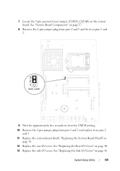
.... "Replacing the System-Board Shield" on pins 2 and 3. 11 Replace the system-board shield. 7 Locate the 3-pin password reset jumper (CMOS_CLEAR) on page 41. System Setup Utility 135
.... "Replacing the System-Board Shield" on pins 2 and 3. 11 Replace the system-board shield. 7 Locate the 3-pin password reset jumper (CMOS_CLEAR) on page 41. System Setup Utility 135

Owners Manual
Page 136
Failure to do so may result in damage to the computer. 16 Connect your computer and devices to electrical outlets, and turn them on page 21. See "Replacing the Back Cover" on . 136 System Setup Utility 14 Replace the rear-stand assembly. See "Replacing the Rear-Stand Assembly" on the computer, replace all screws and ensure that no stray screws remain inside the computer. CAUTION: Before turning on page 36. 15 Replace the back cover.
Failure to do so may result in damage to the computer. 16 Connect your computer and devices to electrical outlets, and turn them on page 21. See "Replacing the Back Cover" on . 136 System Setup Utility 14 Replace the rear-stand assembly. See "Replacing the Rear-Stand Assembly" on the computer, replace all screws and ensure that no stray screws remain inside the computer. CAUTION: Before turning on page 36. 15 Replace the back cover.


