
Owners Manual
Page 4
Replacing the Optical Drive 29 6 Memory Module(s 31 Removing Memory Module(s 31 Replacing Memory Module(s 33 7 Rear-Stand Assembly 35 Removing the Rear-Stand Assembly 35 Replacing the Rear-Stand Assembly 36 8 VESA Mount 37 Removing the VESA Mount 37 Replacing the VESA Mount 38 9 I/O Cover 39 Rear I/O Cover 39 Removing the Rear I/O Cover 39 Replacing the Rear I/O Cover 40 Side I/O Cover 41 Removing the Side I/O Cover 41 Replacing the Side I/O Cover 41 10 Audio Video Board (Optional 43 Removing the Audio Video (AV) Board 43 4 Contents
Replacing the Optical Drive 29 6 Memory Module(s 31 Removing Memory Module(s 31 Replacing Memory Module(s 33 7 Rear-Stand Assembly 35 Removing the Rear-Stand Assembly 35 Replacing the Rear-Stand Assembly 36 8 VESA Mount 37 Removing the VESA Mount 37 Replacing the VESA Mount 38 9 I/O Cover 39 Rear I/O Cover 39 Removing the Rear I/O Cover 39 Replacing the Rear I/O Cover 40 Side I/O Cover 41 Removing the Side I/O Cover 41 Replacing the Side I/O Cover 41 10 Audio Video Board (Optional 43 Removing the Audio Video (AV) Board 43 4 Contents
Owners Manual
Page 5
Replacing the Audio Video (AV) Board 45 11 Converter Board 47 Removing the Converter Board 47 Replacing the Converter Board 48 12 B-CAS Card (Optional 51 Removing the B-CAS Card 51 Replacing the B-CAS Card 52 13 System-Board Shield 53 Removing the System-Board Shield 53 Replacing the System-Board Shield 54 14 Coin-Cell Battery 57 Removing the Coin-Cell Battery 57 Replacing the Coin-Cell Battery 58 15 Wireless Mini-Card(s 61 Removing the Mini-Card(s 61 Replacing the Mini-Card(s 63 Contents 5
Replacing the Audio Video (AV) Board 45 11 Converter Board 47 Removing the Converter Board 47 Replacing the Converter Board 48 12 B-CAS Card (Optional 51 Removing the B-CAS Card 51 Replacing the B-CAS Card 52 13 System-Board Shield 53 Removing the System-Board Shield 53 Replacing the System-Board Shield 54 14 Coin-Cell Battery 57 Removing the Coin-Cell Battery 57 Replacing the Coin-Cell Battery 58 15 Wireless Mini-Card(s 61 Removing the Mini-Card(s 61 Replacing the Mini-Card(s 63 Contents 5
Owners Manual
Page 43
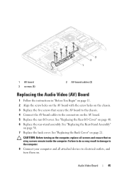
... "Removing the Back Cover" on page 39. 5 Remove the three screws that is not authorized by Dell is not covered by periodically touching an unpainted metal surface (such as a connector on your computer. Audio Video Board 43 Damage due to servicing that secure the AV-board shield to the chassis. 6 Lift the...
... "Removing the Back Cover" on page 39. 5 Remove the three screws that is not authorized by Dell is not covered by periodically touching an unpainted metal surface (such as a connector on your computer. Audio Video Board 43 Damage due to servicing that secure the AV-board shield to the chassis. 6 Lift the...
Owners Manual
Page 44
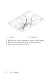
1 2 1 screws (3) 2 AV-board shield 7 Disconnect the AV-board cables from the connectors on the AV board. 8 Remove the five screws that secure the AV board to the chassis. 9 Lift the AV board away from the chassis. 44 Audio Video Board
1 2 1 screws (3) 2 AV-board shield 7 Disconnect the AV-board cables from the connectors on the AV board. 8 Remove the five screws that secure the AV board to the chassis. 9 Lift the AV board away from the chassis. 44 Audio Video Board
Owners Manual
Page 45
.... 5 Replace the rear I /O Cover" on page 40. 6 Replace the rear-stand assembly. CAUTION: Before turning on page 21. Audio Video Board 45 3 2 1 1 AV board 3 screws (5) 2 AV-board cables (2) Replacing the Audio Video (AV) Board 1 Follow the instructions in damage to the computer. 8 Connect your computer and all screws and ensure that secure...
.... 5 Replace the rear I /O Cover" on page 40. 6 Replace the rear-stand assembly. CAUTION: Before turning on page 21. Audio Video Board 45 3 2 1 1 AV board 3 screws (5) 2 AV-board cables (2) Replacing the Audio Video (AV) Board 1 Follow the instructions in damage to the computer. 8 Connect your computer and all screws and ensure that secure...
Owners Manual
Page 109
.... Damage due to step 5 in "Before You Begin" on page 43. 11 Remove the processor heat-sink fan. See "Removing the Audio Video (AV) Board" on page 11. 2 Remove the back cover. Display Assembly Removing the Display Assembly 1 Follow the instructions in "Removing the Optical...Drive" on page 27. 6 Remove the VESA mount. Display 109 For additional safety best practices information, see the Regulatory Compliance Homepage at dell.com/regulatory_compliance. CAUTION: To avoid electrostatic discharge, ground yourself by using a wrist grounding strap or by your warranty. See "Removing the...
.... Damage due to step 5 in "Before You Begin" on page 43. 11 Remove the processor heat-sink fan. See "Removing the Audio Video (AV) Board" on page 11. 2 Remove the back cover. Display Assembly Removing the Display Assembly 1 Follow the instructions in "Removing the Optical...Drive" on page 27. 6 Remove the VESA mount. Display 109 For additional safety best practices information, see the Regulatory Compliance Homepage at dell.com/regulatory_compliance. CAUTION: To avoid electrostatic discharge, ground yourself by using a wrist grounding strap or by your warranty. See "Removing the...
Owners Manual
Page 112
... and LVDS cable through the routing guides. 8 Connect the cables to the connectors on page 29. 16 Replace the VESA mount. See "Replacing the Audio Video (AV) Board" on page 38. 17 Replace the rear-stand assembly. See "Replacing the VESA Mount" on page 45. 12 Replace the system-board shield...
... and LVDS cable through the routing guides. 8 Connect the cables to the connectors on page 29. 16 Replace the VESA mount. See "Replacing the Audio Video (AV) Board" on page 38. 17 Replace the rear-stand assembly. See "Replacing the VESA Mount" on page 45. 12 Replace the system-board shield...
Owners Manual
Page 121
See "Removing the Back Cover" on page 43. 11 Remove the middle frame. See "Removing the Audio Video (AV) Board" on page 19. 3 Remove the rear-stand assembly. See "Removing the Feet" on page 69. 5 Follow the instructions from step 3 to step 5 in "... that secure the speaker cover to the chassis. 13 Release the four tabs that secure the speaker cover to servicing that is not authorized by Dell is not covered by periodically touching an unpainted metal surface (such as a connector on page 37. 7 Remove the rear I /O cover. CAUTION: Only a certified service technician...
See "Removing the Back Cover" on page 43. 11 Remove the middle frame. See "Removing the Audio Video (AV) Board" on page 19. 3 Remove the rear-stand assembly. See "Removing the Feet" on page 69. 5 Follow the instructions from step 3 to step 5 in "... that secure the speaker cover to the chassis. 13 Release the four tabs that secure the speaker cover to servicing that is not authorized by Dell is not covered by periodically touching an unpainted metal surface (such as a connector on page 37. 7 Remove the rear I /O cover. CAUTION: Only a certified service technician...
Owners Manual
Page 122
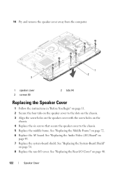
... the chassis. 3 Align the screw holes on the speaker cover with the screw holes on page 72. 6 Replace the AV board. See "Replacing the Audio Video (AV) Board" on page 40. 122 Speaker Cover
... the chassis. 3 Align the screw holes on the speaker cover with the screw holes on page 72. 6 Replace the AV board. See "Replacing the Audio Video (AV) Board" on page 40. 122 Speaker Cover


