Setup Guide
Page 5
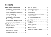
...System 9 Create System Recovery Media (Recommended 10 Enable or Disable Wireless (Optional 12 Connect to the Internet (Optional 14 Using Your Inspiron Laptop 18 Right View Features 18 Left View Features 20 Front View Features 22 Status Lights and Indicators 24 Computer Base Features 26 ...Gestures 28 Multimedia Control Keys 30 Using the Optical Drive 32 Display Features 34 Removing and Replacing the Battery 36 Software Features 38 Dell DataSafe Online Backup 39 Dell Dock 40 Solving Problems 41 Beep Codes 41 Network Problems 42 Power Problems 43 Memory Problems 44 Lockups...
...System 9 Create System Recovery Media (Recommended 10 Enable or Disable Wireless (Optional 12 Connect to the Internet (Optional 14 Using Your Inspiron Laptop 18 Right View Features 18 Left View Features 20 Front View Features 22 Status Lights and Indicators 24 Computer Base Features 26 ...Gestures 28 Multimedia Control Keys 30 Using the Optical Drive 32 Display Features 34 Removing and Replacing the Battery 36 Software Features 38 Dell DataSafe Online Backup 39 Dell Dock 40 Solving Problems 41 Beep Codes 41 Network Problems 42 Power Problems 43 Memory Problems 44 Lockups...
Setup Guide
Page 23
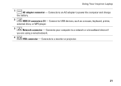
Connects to an AC adapter to a monitor or projector. 21 Connects to power the computer and charge the battery. 2 USB 2.0 connectors (3) - Using Your Inspiron Laptop 1 AC adapter connector - Connects your computer to USB devices, such as a mouse, keyboard, printer, external drive, or MP3 player. 3 Network connector - Connect to a network or a broadband device if you are using a wired network. 4 VGA connector -
Connects to an AC adapter to a monitor or projector. 21 Connects to power the computer and charge the battery. 2 USB 2.0 connectors (3) - Using Your Inspiron Laptop 1 AC adapter connector - Connects your computer to USB devices, such as a mouse, keyboard, printer, external drive, or MP3 player. 3 Network connector - Connect to a network or a broadband device if you are using a wired network. 4 VGA connector -
Setup Guide
Page 25
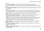
Using Your Inspiron Laptop 1 Power status light - Blinks to a microphone or inputs signal for use when no media card is powered using the AC adapter. 4 3-in /Microphone connector - NOTE: The battery is charging when the computer is installed in the media card slot. Turns on ... or sound system. 7 Audio in -1 Media Card Reader - Connects to indicate hard drive activity when the computer reads or writes data. 3 Battery status light - Save the blank for video conferencing and voice recording. 6 Audio out/Headphone connector - NOTE: Your computer ships with audio programs....
Using Your Inspiron Laptop 1 Power status light - Blinks to a microphone or inputs signal for use when no media card is powered using the AC adapter. 4 3-in /Microphone connector - NOTE: The battery is charging when the computer is installed in the media card slot. Turns on ... or sound system. 7 Audio in -1 Media Card Reader - Connects to indicate hard drive activity when the computer reads or writes data. 3 Battery status light - Save the blank for video conferencing and voice recording. 6 Audio out/Headphone connector - NOTE: Your computer ships with audio programs....

Setup Guide
Page 26
Using Your Inspiron Laptop Status Lights and Indicators Battery Status Light Indicator light status Computer state(s) AC adapter solid white on/standby/off/ hibernate off on/standby/off/ hibernate Battery solid amber on/standby off on/standby/off/ hibernate off/hibernate Battery charge level 98% 10%
Using Your Inspiron Laptop Status Lights and Indicators Battery Status Light Indicator light status Computer state(s) AC adapter solid white on/standby/off/ hibernate off on/standby/off/ hibernate Battery solid amber on/standby off on/standby/off/ hibernate off/hibernate Battery charge level 98% 10%
Setup Guide
Page 38
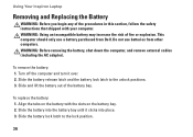
...batteries from Dell. Do not use a battery purchased from other computers. WARNING: Before removing the battery, shut down the computer, and remove external cables (including the AC adapter). Slide the battery release latch and the battery lock latch to the lock position. 36 To remove the battery: 1. Slide the battery into the battery... bay until it over. 2. Slide and lift the battery out of fire or explosion. To replace the battery: 1. Using Your Inspiron Laptop Removing and Replacing the Battery WARNING: Before you...
...batteries from Dell. Do not use a battery purchased from other computers. WARNING: Before removing the battery, shut down the computer, and remove external cables (including the AC adapter). Slide the battery release latch and the battery lock latch to the lock position. 36 To remove the battery: 1. Slide the battery into the battery... bay until it over. 2. Slide and lift the battery out of fire or explosion. To replace the battery: 1. Using Your Inspiron Laptop Removing and Replacing the Battery WARNING: Before you...
Setup Guide
Page 51
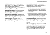
... source to function properly. Hard-disk drive failure - Using Support Tools No boot device available - Replace the battery (see the Service Manual at support.dell.com/manuals). Contact Dell (see "Contacting Dell" on page 70). No bootable partition on page 70). A chip on your device has two USB cables,...needs more power for it to connect the USB device, or if your hard drive or at support.dell.com/manuals). Possible system board failure or RTC battery low. Contact Dell (see "Contacting Dell" on hard drive, the hard drive cable is loose, or no bootable device exists. • ...
... source to function properly. Hard-disk drive failure - Using Support Tools No boot device available - Replace the battery (see the Service Manual at support.dell.com/manuals). Contact Dell (see "Contacting Dell" on page 70). No bootable partition on page 70). A chip on your device has two USB cables,...needs more power for it to connect the USB device, or if your hard drive or at support.dell.com/manuals). Possible system board failure or RTC battery low. Contact Dell (see "Contacting Dell" on hard drive, the hard drive cable is loose, or no bootable device exists. • ...
Setup Guide
Page 80
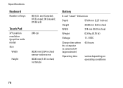
and Canada); 87 (Europe); 90 (Japan); 87 (Brazil) 240 cpi 90.00 mm (3.54 inches) sensor-active area 46.00 mm (1.81 inches) rectangle Battery 6-cell "smart" lithium ion Depth 57.64 mm (2.27 inches) Height 22.80 mm (0.9 inches) Width 214 mm (8.43 inches) Weight 0.34 kg (0.75 lb) Voltage 11.1 VDC Charge time when the computer is powered off (approximate) 4.5 hours Operating time varies depending on operating conditions 78 Specifications Keyboard Number of keys Touch Pad X/Y position resolution (graphics table mode) Size Width Height 86 (U.S.
and Canada); 87 (Europe); 90 (Japan); 87 (Brazil) 240 cpi 90.00 mm (3.54 inches) sensor-active area 46.00 mm (1.81 inches) rectangle Battery 6-cell "smart" lithium ion Depth 57.64 mm (2.27 inches) Height 22.80 mm (0.9 inches) Width 214 mm (8.43 inches) Weight 0.34 kg (0.75 lb) Voltage 11.1 VDC Charge time when the computer is powered off (approximate) 4.5 hours Operating time varies depending on operating conditions 78 Specifications Keyboard Number of keys Touch Pad X/Y position resolution (graphics table mode) Size Width Height 86 (U.S.

Setup Guide
Page 81
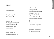
AC Adapter Input voltage 100-240 VAC Input current 1.5 A/1.6 A/1.7A Input frequency 50-60 Hz Output power 65 W Output current 4.43 A (maximum at 4-second pulse) 3.34 A (continuous) Rated output voltage 19.5 VDC Temperature range: Operating 0° to 40°C (32° to 104°F) Storage -40° to 70°C (-40° to 158°F) Specifications Physical Height Width Depth Weight (with 6-cell battery) 37.74 mm to 40.22 mm (1.48 inches to 1.58 inches) 378 mm (14.88 inches) 245 mm (9.64 inches) configurable to less than 2.58 kg (5.7 lbs) 79
AC Adapter Input voltage 100-240 VAC Input current 1.5 A/1.6 A/1.7A Input frequency 50-60 Hz Output power 65 W Output current 4.43 A (maximum at 4-second pulse) 3.34 A (continuous) Rated output voltage 19.5 VDC Temperature range: Operating 0° to 40°C (32° to 104°F) Storage -40° to 70°C (-40° to 158°F) Specifications Physical Height Width Depth Weight (with 6-cell battery) 37.74 mm to 40.22 mm (1.48 inches to 1.58 inches) 378 mm (14.88 inches) 245 mm (9.64 inches) configurable to less than 2.58 kg (5.7 lbs) 79
Setup Guide
Page 85
Index A airflow, allowing 5 B battery status light 24 before you call 68 C calling Dell 68 CDs, playing and creating 38 computer capabilities 38 computer, setting up 5 customer service 64 D damage, avoiding 5 DataSafe Online Backup 39 DellConnect 64 Dell Diagnostics 51 Dell Factory Image Restore 61 Dell Support Center 47 Diagnostic Checklist 69 drivers and downloads 73 DVDs, playing and creating 38 E email addresses for technical support 65 F finding more information 72 FTP login, anonymous 65 83 INSPIRON
Index A airflow, allowing 5 B battery status light 24 before you call 68 C calling Dell 68 CDs, playing and creating 38 computer capabilities 38 computer, setting up 5 customer service 64 D damage, avoiding 5 DataSafe Online Backup 39 DellConnect 64 Dell Diagnostics 51 Dell Factory Image Restore 61 Dell Support Center 47 Diagnostic Checklist 69 drivers and downloads 73 DVDs, playing and creating 38 E email addresses for technical support 65 F finding more information 72 FTP login, anonymous 65 83 INSPIRON
Service Guide
Page 1
... license; WARNING: A WARNING indicates a potential for property damage, personal injury, or death. P07F003 Reproduction of Dell Inc.; Dell™ Inspiron™ N5020/M5030/N5030 Service Manual Before You Begin Battery Keyboard Palm Rest Speakers Power Button Module Memory Module(s) Hard Drive Optical Drive Wireless Mini-Card Internal Module With Bluetooth® Wireless Technology Coin-Cell...
... license; WARNING: A WARNING indicates a potential for property damage, personal injury, or death. P07F003 Reproduction of Dell Inc.; Dell™ Inspiron™ N5020/M5030/N5030 Service Manual Before You Begin Battery Keyboard Palm Rest Speakers Power Button Module Memory Module(s) Hard Drive Optical Drive Wireless Mini-Card Internal Module With Bluetooth® Wireless Technology Coin-Cell...

Service Guide
Page 3
... scratched. 2. Turn the computer top-side up, open the display, and press the power button to Contents Page Remove the battery (see Removing the Battery) before you begin working inside the computer. 1. CAUTION: To disconnect a network cable, first unplug the cable from your computer... devices. Turn off your computer. Ensure that the work surface is flat and clean to the system board, remove the main battery (see Removing the Battery). 8. CAUTION: To avoid damaging the computer, perform the following steps before working inside the computer. 7. CAUTION: To help prevent...
... scratched. 2. Turn the computer top-side up, open the display, and press the power button to Contents Page Remove the battery (see Removing the Battery) before you begin working inside the computer. 1. CAUTION: To disconnect a network cable, first unplug the cable from your computer... devices. Turn off your computer. Ensure that the work surface is flat and clean to the system board, remove the main battery (see Removing the Battery). 8. CAUTION: To avoid damaging the computer, perform the following steps before working inside the computer. 7. CAUTION: To help prevent...

Service Guide
Page 5
...palm rest (see Removing the Keyboard). 4. Back to Contents Page Internal Module With Bluetooth® Wireless Technology Dell™ Inspiron™ N5020/M5030/N5030 Service Manual Removing the Bluetooth Module Replacing the Bluetooth Module WARNING: Before working inside your computer, read the ... the system board. 1 Bluetooth module 2 screw Replacing the Bluetooth Module 1. For additional safety best practices information, see Removing the Battery). 3. CAUTION: To help prevent damage to the connector on the system board and press the Bluetooth module until it is not covered...
...palm rest (see Removing the Keyboard). 4. Back to Contents Page Internal Module With Bluetooth® Wireless Technology Dell™ Inspiron™ N5020/M5030/N5030 Service Manual Removing the Bluetooth Module Replacing the Bluetooth Module WARNING: Before working inside your computer, read the ... the system board. 1 Bluetooth module 2 screw Replacing the Bluetooth Module 1. For additional safety best practices information, see Removing the Battery). 3. CAUTION: To help prevent damage to the connector on the system board and press the Bluetooth module until it is not covered...

Service Guide
Page 6
Replace the palm rest (see Replacing the Battery). Replace the battery (see Replacing the Palm Rest). 5. CAUTION: Before turning on the computer, replace all screws and ensure that no stray screws remain inside the computer. 4. Replace the keyboard (see Replacing the Keyboard). 6. Back to the computer. Failure to do so may result in damage to Contents Page
Replace the palm rest (see Replacing the Battery). Replace the battery (see Replacing the Palm Rest). 5. CAUTION: Before turning on the computer, replace all screws and ensure that no stray screws remain inside the computer. 4. Replace the keyboard (see Replacing the Keyboard). 6. Back to the computer. Failure to do so may result in damage to Contents Page

Service Guide
Page 7
... your computer. Remove the palm rest (see Replacing the Display Assembly). Damage due to Contents Page Camera Module Dell™ Inspiron™ N5020/M5030/N5030 Service Manual Removing the Camera Module Replacing the Camera Module WARNING: Before working inside your computer, read the safety...latches until it to the system board, remove the main battery (see Removing the Battery) before working inside the computer. Back to servicing that is not authorized by Dell™ is fully seated. 3. Remove the battery (see Replacing the Display Bezel). 4. Release the camera module...
... your computer. Remove the palm rest (see Replacing the Display Assembly). Damage due to Contents Page Camera Module Dell™ Inspiron™ N5020/M5030/N5030 Service Manual Removing the Camera Module Replacing the Camera Module WARNING: Before working inside your computer, read the safety...latches until it to the system board, remove the main battery (see Removing the Battery) before working inside the computer. Back to servicing that is not authorized by Dell™ is fully seated. 3. Remove the battery (see Replacing the Display Bezel). 4. Release the camera module...

Service Guide
Page 8
CAUTION: Before turning on the computer, replace all screws and ensure that no stray screws remain inside the computer. Back to the computer. Replace the battery (see Replacing the Palm Rest). 6. Replace the palm rest (see Replacing the Battery). 5. Replace the keyboard (see Replacing the Keyboard). 7. Failure to do so may result in damage to Contents Page
CAUTION: Before turning on the computer, replace all screws and ensure that no stray screws remain inside the computer. Back to the computer. Replace the battery (see Replacing the Palm Rest). 6. Replace the palm rest (see Replacing the Battery). 5. Replace the keyboard (see Replacing the Keyboard). 7. Failure to do so may result in damage to Contents Page
Service Guide
Page 9
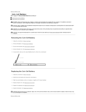
... computer. Failure to do so may result in damage to Contents Page Back to Contents Page Coin-Cell Battery Dell™ Inspiron™ N5020/M5030/N5030 Service Manual Removing the Coin-Cell Battery Replacing the Coin-Cell Battery WARNING: Before working inside your computer, read the safety information that shipped with the positive side facing up...
... computer. Failure to do so may result in damage to Contents Page Back to Contents Page Coin-Cell Battery Dell™ Inspiron™ N5020/M5030/N5030 Service Manual Removing the Coin-Cell Battery Replacing the Coin-Cell Battery WARNING: Before working inside your computer, read the safety information that shipped with the positive side facing up...
Service Guide
Page 10
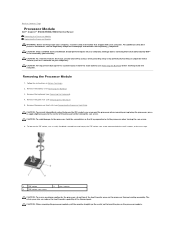
...: When removing the processor module, pull the module straight up. CAUTION: To help prevent damage to the system board, remove the main battery (see Removing the Keyboard). 4. CAUTION: To avoid damage to the processor, hold the screwdriver so that shipped with your warranty. CAUTION:...the processor, press to apply slight pressure to the center of the thermal pads. Back to Contents Page Processor Module Dell™ Inspiron™ N5020/M5030/N5030 Service Manual Removing the Processor Module Replacing the Processor Module WARNING: Before working inside your computer, read the safety ...
...: When removing the processor module, pull the module straight up. CAUTION: To help prevent damage to the system board, remove the main battery (see Removing the Keyboard). 4. CAUTION: To avoid damage to the processor, hold the screwdriver so that shipped with your warranty. CAUTION:...the processor, press to apply slight pressure to the center of the thermal pads. Back to Contents Page Processor Module Dell™ Inspiron™ N5020/M5030/N5030 Service Manual Removing the Processor Module Replacing the Processor Module WARNING: Before working inside your computer, read the safety ...
Service Guide
Page 11
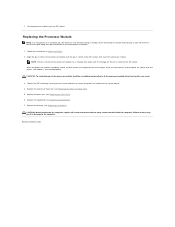
... You Begin. 2. When the processor module is properly seated, all screws and ensure that no stray screws remain inside the computer. Replace the battery (see Replacing the Palm Rest). 6. If one or more corners of the ZIF socket, then insert the processor module. CAUTION: To avoid... damage to the processor module, hold the screwdriver perpendicular to Contents Page Replace the palm rest (see Replacing the Battery). Failure to the computer. 7. Align the pin-1 corner of the processor module has a triangle that aligns with the triangle on the computer,...
... You Begin. 2. When the processor module is properly seated, all screws and ensure that no stray screws remain inside the computer. Replace the battery (see Replacing the Palm Rest). 6. If one or more corners of the ZIF socket, then insert the processor module. CAUTION: To avoid... damage to the processor module, hold the screwdriver perpendicular to Contents Page Replace the palm rest (see Replacing the Battery). Failure to the computer. 7. Align the pin-1 corner of the processor module has a triangle that aligns with the triangle on the computer,...
Service Guide
Page 12
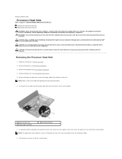
...read the safety information that secure the processor heat sink to the system board, remove the main battery (see Removing the Battery) before disconnecting the cables. 6. Remove the battery (see Removing the Palm Rest). 5. CAUTION: Only a certified service technician should perform repairs on...captive screws that shipped with your computer. Remove the palm rest (see Removing the Battery). 3. Back to Contents Page Processor Heat Sink Dell™ Inspiron™ N5020/M5030/N5030 Service Manual Removing the Processor Heat Sink Replacing the Processor Heat Sink WARNING: Before working...
...read the safety information that secure the processor heat sink to the system board, remove the main battery (see Removing the Battery) before disconnecting the cables. 6. Remove the battery (see Removing the Palm Rest). 5. CAUTION: Only a certified service technician should perform repairs on...captive screws that shipped with your computer. Remove the palm rest (see Removing the Battery). 3. Back to Contents Page Processor Heat Sink Dell™ Inspiron™ N5020/M5030/N5030 Service Manual Removing the Processor Heat Sink Replacing the Processor Heat Sink WARNING: Before working...
Service Guide
Page 13
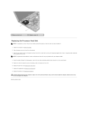
...may result in Before You Begin. 2. Replace the adhesive tape that secures the display cable to Contents Page Replace the keyboard (see Replacing the Battery). Place the processor heat sink on the your computer model. 4. Route the cables through the routing guides. 1 processor heat sink 2 captive ... all screws and ensure that no stray screws remain inside the computer. Follow the instructions in damage to replace it. 1. Replace the battery (see Replacing the Keyboard). 8. Align the four captive screws on the processor heat sink with the screw holes on the system board ...
...may result in Before You Begin. 2. Replace the adhesive tape that secures the display cable to Contents Page Replace the keyboard (see Replacing the Battery). Place the processor heat sink on the your computer model. 4. Route the cables through the routing guides. 1 processor heat sink 2 captive ... all screws and ensure that no stray screws remain inside the computer. Follow the instructions in damage to replace it. 1. Replace the battery (see Replacing the Keyboard). 8. Align the four captive screws on the processor heat sink with the screw holes on the system board ...


