Quick Start Guide
Page 7
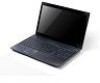
...(SD), MultiMediaCard (MMC). Turns the computer on and off. Charging: The light shows amber when the battery is active. Delivers audio output. The left and right buttons function like a computer mouse. Internal microphone...Display screen HDD indicator Description Also called Liquid-Crystal Display (LCD), displays computer output. Indicates when the hard disk drive is charging. 2. Battery indicator Click buttons (left and right mouse buttons. Communication indicator Power button / indicator Keyboard Power indicator Indicates the computer's wireless connectivity device status...
...(SD), MultiMediaCard (MMC). Turns the computer on and off. Charging: The light shows amber when the battery is active. Delivers audio output. The left and right buttons function like a computer mouse. Internal microphone...Display screen HDD indicator Description Also called Liquid-Crystal Display (LCD), displays computer output. Indicates when the hard disk drive is charging. 2. Battery indicator Click buttons (left and right mouse buttons. Communication indicator Power button / indicator Keyboard Power indicator Indicates the computer's wireless connectivity device status...
Quick Start Guide
Page 9
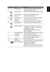
Headphone/speaker/ Connects to an Ethernet 10/100/1000- English 7 Rear view # Item 1 Battery bay Left view 1 Description Houses the computer's battery pack. 1 # Icon 1 Item DC-in jack 2 34 56 Description Connects to an AC adapter. 2 External display Connects to a display device (e.g., (VGA) port external monitor, LCD ...
Headphone/speaker/ Connects to an Ethernet 10/100/1000- English 7 Rear view # Item 1 Battery bay Left view 1 Description Houses the computer's battery pack. 1 # Icon 1 Item DC-in jack 2 34 56 Description Connects to an AC adapter. 2 External display Connects to a display device (e.g., (VGA) port external monitor, LCD ...
Quick Start Guide
Page 11
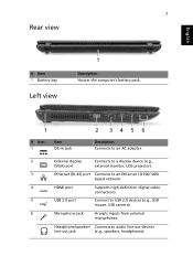
English 9 Base view 1 2 4 3 # Icon 1 Item Battery bay Description Houses the computer's battery pack. 2 Battery release latch Releases the battery for removal. 3 Memory Houses the computer's main memory. compartment Hard disk bay - Environment • Temperature: • Operating: 5 °C to 35 °C • Non-operating: -20 °C to 65 °C • Humidity (non-condensing): • Operating: 20% to 80% • Non-operating: 20% to 80% Main Houses the computer's hard disk (secured with screws). 4 Battery lock Locks the battery in position.
English 9 Base view 1 2 4 3 # Icon 1 Item Battery bay Description Houses the computer's battery pack. 2 Battery release latch Releases the battery for removal. 3 Memory Houses the computer's main memory. compartment Hard disk bay - Environment • Temperature: • Operating: 5 °C to 35 °C • Non-operating: -20 °C to 65 °C • Humidity (non-condensing): • Operating: 20% to 80% • Non-operating: 20% to 80% Main Houses the computer's hard disk (secured with screws). 4 Battery lock Locks the battery in position.
Service Guide
Page 7
...Features 1 System Block Diagram 6 UMA 6 Discrete (nVidia 7 Discrete (ATI 8 Your Acer Notebook tour 9 Top View 9 Rear view 10 Left View 11 Right View 12 ... Specifications and Configurations 19 System Utilities 31 BIOS Setup Utility 31 Navigating the BIOS Utility 31 Aspire 5742/5742G/5742Z/5742ZG BIOS 32 Information 32 Main 33 Security 34 Boot 37 Exit 38 BIOS ... 48 Disassembly Process 49 External Module Disassembly Process 50 External Modules Disassembly Flowchart 50 Removing the Battery Pack 51 Removing the SD Dummy Card 52 Removing the ODD Module 53 Removing the Logic ...
...Features 1 System Block Diagram 6 UMA 6 Discrete (nVidia 7 Discrete (ATI 8 Your Acer Notebook tour 9 Top View 9 Rear view 10 Left View 11 Right View 12 ... Specifications and Configurations 19 System Utilities 31 BIOS Setup Utility 31 Navigating the BIOS Utility 31 Aspire 5742/5742G/5742Z/5742ZG BIOS 32 Information 32 Main 33 Security 34 Boot 37 Exit 38 BIOS ... 48 Disassembly Process 49 External Module Disassembly Process 50 External Modules Disassembly Flowchart 50 Removing the Battery Pack 51 Removing the SD Dummy Card 52 Removing the ODD Module 53 Removing the Logic ...
Service Guide
Page 8
... Only 137 Replacing the Touchpad FFC 139 Replacing the Power Board 140 Replacing the Speaker Module 141 Replacing the Upper Cover 142 Replacing the RTC Battery (UMA Only 146 Replacing the HDD Module 147 Replacing the WLAN Module 149 Replacing the DIMM Modules 151 Replacing the 3G Cover (Discrete Only 152...
... Only 137 Replacing the Touchpad FFC 139 Replacing the Power Board 140 Replacing the Speaker Module 141 Replacing the Upper Cover 142 Replacing the RTC Battery (UMA Only 146 Replacing the HDD Module 147 Replacing the WLAN Module 149 Replacing the DIMM Modules 151 Replacing the 3G Cover (Discrete Only 152...
Service Guide
Page 13
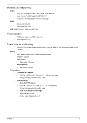
...; ACPI 3.0 CPU power management standard: supports Stand-by and Hibernation power-saving modes Battery • 48.8 W 4400 mAh 6-cell Li-ion standard battery pack • ENERGY STAR® • 5742, 5742Z • Battery life: 3.5 hours • 5742G, 5742ZG • Battery life: 3 hours Power adapter • 3-pin 65 W AC adapter: • 108 (W) x...adapter: • 133 (W) x 59 (D) x 31 (H) mm (5.23 x 2.32 x 1.22 inches) • 390 g (0.86 lbs.) with 180 cm DC cable • Acer QuicCharge™ technology: • 80% charge in 1 hour • 2-hour rapid charge system-off Chapter 1 3
...; ACPI 3.0 CPU power management standard: supports Stand-by and Hibernation power-saving modes Battery • 48.8 W 4400 mAh 6-cell Li-ion standard battery pack • ENERGY STAR® • 5742, 5742Z • Battery life: 3.5 hours • 5742G, 5742ZG • Battery life: 3 hours Power adapter • 3-pin 65 W AC adapter: • 108 (W) x...adapter: • 133 (W) x 59 (D) x 31 (H) mm (5.23 x 2.32 x 1.22 inches) • 390 g (0.86 lbs.) with 180 cm DC cable • Acer QuicCharge™ technology: • 80% charge in 1 hour • 2-hour rapid charge system-off Chapter 1 3
Service Guide
Page 14
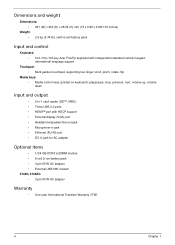
...(D) x 25/34 (H) mm (15 x 9.96 x 0.98/1.33 inches) Weight: • 2.6 kg (5.74 lbs.) with 6-cell battery pack Input and control Keyboard: • 103-/104-/107-key Acer FineTip keyboard with independent standard numeric keypad, international language support Touchpad: • Multi-gesture touchpad, supporting two-finger scroll, pinch... Ethernet (RJ-45) port • DC-in jack for AC adapter Optional items • 1/2/4 GB DDR3 soDIMM module • 6-cell Li-ion battery pack • 3-pin 65 W AC adapter • External USB 56K modem 5742G, 5742ZG • 3-pin 90 W AC adapter Warranty •...
...(D) x 25/34 (H) mm (15 x 9.96 x 0.98/1.33 inches) Weight: • 2.6 kg (5.74 lbs.) with 6-cell battery pack Input and control Keyboard: • 103-/104-/107-key Acer FineTip keyboard with independent standard numeric keypad, international language support Touchpad: • Multi-gesture touchpad, supporting two-finger scroll, pinch... Ethernet (RJ-45) port • DC-in jack for AC adapter Optional items • 1/2/4 GB DDR3 soDIMM module • 6-cell Li-ion battery pack • 3-pin 65 W AC adapter • External USB 56K modem 5742G, 5742ZG • 3-pin 90 W AC adapter Warranty •...

Service Guide
Page 20
... charged: The light shows blue when in -1 card reader Accepts Secure Digital (SD), MultiMediaCard (MMC). Charging: The light shows amber when the battery is charging. 2. Battery indicator Indicates the computer's battery status. 1. NOTE: The 2-in1 card reader will be on the front right for sound recording. 2-in AC mode. 7 Click buttons (left The...
... charged: The light shows blue when in -1 card reader Accepts Secure Digital (SD), MultiMediaCard (MMC). Charging: The light shows amber when the battery is charging. 2. Battery indicator Indicates the computer's battery status. 1. NOTE: The 2-in1 card reader will be on the front right for sound recording. 2-in AC mode. 7 Click buttons (left The...

Service Guide
Page 23
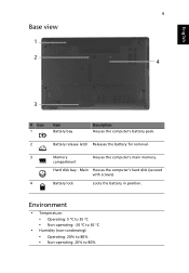
Locks the battery in position. Base view 1 2 4 No. 1 2 3 4 3 Icon Item Battery bay Description Houses the computer's battery pack. Battery release latch Memory compartment Hard disk bay Main Battery lock Releases the battery for removal. Chapter 1 13 Houses the computer's main memory. Houses the computer's hard disk (secured with screws).
Locks the battery in position. Base view 1 2 4 No. 1 2 3 4 3 Icon Item Battery bay Description Houses the computer's battery pack. Battery release latch Memory compartment Hard disk bay Main Battery lock Releases the battery for removal. Chapter 1 13 Houses the computer's main memory. Houses the computer's hard disk (secured with screws).
Service Guide
Page 24
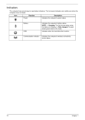
NOTE: 1. Icon Function Power Description Indicates the computer's power status. Charging: The light shows amber when the battery is active. Fully charged: The light shows green when in AC mode. Communication indicator Indicates the computer's wireless connectivity device status. 14 Chapter 1 Battery HDD Indicates the computer's battery status. Indicates when the hard disk drive is charging. 2. The front panel indicators are visible even when the computer cover is closed. Indicators The computer has several easy-to-read status indicators.
NOTE: 1. Icon Function Power Description Indicates the computer's power status. Charging: The light shows amber when the battery is active. Fully charged: The light shows green when in AC mode. Communication indicator Indicates the computer's wireless connectivity device status. 14 Chapter 1 Battery HDD Indicates the computer's battery status. Indicates when the hard disk drive is charging. 2. The front panel indicators are visible even when the computer cover is closed. Indicators The computer has several easy-to-read status indicators.

Service Guide
Page 35
... Mbps, up to 270 Mbps for Draft-N Protocol 802.11 b+g, Draft-N Interface PCI bus (mini PCI socket for wireless module) Battery Item Vendor & model name Battery Type Pack capacity Number of battery cell Package configuration Sanyo AS10D, Simplo AS10D, Sony AS10D, Samsung AS10D, Panasonic AS10D Li-ion 2200 mAh 6 3S2P Specification Chapter 1 25
... Mbps, up to 270 Mbps for Draft-N Protocol 802.11 b+g, Draft-N Interface PCI bus (mini PCI socket for wireless module) Battery Item Vendor & model name Battery Type Pack capacity Number of battery cell Package configuration Sanyo AS10D, Simplo AS10D, Sony AS10D, Samsung AS10D, Panasonic AS10D Li-ion 2200 mAh 6 3S2P Specification Chapter 1 25

Service Guide
Page 39
... low power state Discharging • Amber and blinking - battery abnormal stop charge or batter in critical low state • Amber color off Charging • Amber solid on - battery charging with AC • Blue color solid on - battery full • Amber blinking - System LED Indicator Item Lock System state ...HDD access state Wireless state Power button backlight Battery state Specification N/A • Blue color solid on: system on • Blue color and amber color off: system off • Amber color blinking...
... low power state Discharging • Amber and blinking - battery abnormal stop charge or batter in critical low state • Amber color off Charging • Amber solid on - battery charging with AC • Blue color solid on - battery full • Amber blinking - System LED Indicator Item Lock System state ...HDD access state Wireless state Power button backlight Battery state Specification N/A • Blue color solid on: system on • Blue color and amber color off: system off • Amber color blinking...

Service Guide
Page 49
... you should create a Crisis Recovery Diskette before you use the Flash utility. Fellow the steps below to update the system BIOS Flash ROM. If the battery pack does not contain enough power to the bootable diskette. 3. NOTE: Please use the AC adaptor power supply when you may not boot the system...
... you should create a Crisis Recovery Diskette before you use the Flash utility. Fellow the steps below to update the system BIOS Flash ROM. If the battery pack does not contain enough power to the bootable diskette. 3. NOTE: Please use the AC adaptor power supply when you may not boot the system...
Service Guide
Page 61
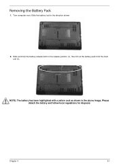
Please detach the battery and follow local regulations for disposal. Turn computer over. Slide the battery lock in the above image. Slide and hold the battery release latch in the release position (1), then lift out the battery pack from the main unit (2). 2 1 NOTE: The battery has been highlighted with a yellow oval as shown in the direction shown. 2. Chapter 3 51 Removing the Battery Pack 1.
Please detach the battery and follow local regulations for disposal. Turn computer over. Slide the battery lock in the above image. Slide and hold the battery release latch in the release position (1), then lift out the battery pack from the main unit (2). 2 1 NOTE: The battery has been highlighted with a yellow oval as shown in the direction shown. 2. Chapter 3 51 Removing the Battery Pack 1.
Service Guide
Page 62
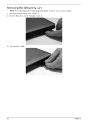
Pull it . 3. See "Removing the Battery Pack" on page 51. 2. Removing the SD Dummy Card NOTE: The model displayed in this service guide may differ in your package. 1. Push the SD dummy card all the way in to the one in color to eject it out from the slot. 52 Chapter 3
Pull it . 3. See "Removing the Battery Pack" on page 51. 2. Removing the SD Dummy Card NOTE: The model displayed in this service guide may differ in your package. 1. Push the SD dummy card all the way in to the one in color to eject it out from the slot. 52 Chapter 3

Service Guide
Page 63
Step ODD Module Size M2.5*8 Quantity 1 3. Screw Type Chapter 3 53 Pull the ODD module out from the chassis. Remove the screw securing the ODD module. See "Removing the Battery Pack" on page 51. 2. Removing the ODD Module 1.
Step ODD Module Size M2.5*8 Quantity 1 3. Screw Type Chapter 3 53 Pull the ODD module out from the chassis. Remove the screw securing the ODD module. See "Removing the Battery Pack" on page 51. 2. Removing the ODD Module 1.
Service Guide
Page 65
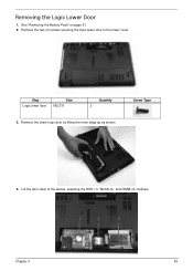
Remove the two (2) screws securing the logic lower door to the lower cover. Remove the lower logic door by lifting the inner edge up as shown. Screw Type 4. Lift the door clear of the device, exposing the HDD (1), WLAN (2), and DIMM (3) modules. 1 2 3 Chapter 3 55 Removing the Logic Lower Door 1. Step Logic lower door Size M2.5*8 Quantity 2 3. See "Removing the Battery Pack" on page 51. 2.
Remove the two (2) screws securing the logic lower door to the lower cover. Remove the lower logic door by lifting the inner edge up as shown. Screw Type 4. Lift the door clear of the device, exposing the HDD (1), WLAN (2), and DIMM (3) modules. 1 2 3 Chapter 3 55 Removing the Logic Lower Door 1. Step Logic lower door Size M2.5*8 Quantity 2 3. See "Removing the Battery Pack" on page 51. 2.
Service Guide
Page 66
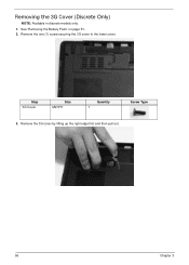
Step 3G Cover Size M2.5*8 Quantity 1 Screw Type 3. Remove the 3G cover by lifting up the right edge first and then pull out. 56 Chapter 3 Remove the one (1) screw securing the 3G cover to the lower cover. See "Removing the Battery Pack" on page 51. 2. Removing the 3G Cover (Discrete Only) NOTE: Available in discrete models only 1.
Step 3G Cover Size M2.5*8 Quantity 1 Screw Type 3. Remove the 3G cover by lifting up the right edge first and then pull out. 56 Chapter 3 Remove the one (1) screw securing the 3G cover to the lower cover. See "Removing the Battery Pack" on page 51. 2. Removing the 3G Cover (Discrete Only) NOTE: Available in discrete models only 1.
Service Guide
Page 67
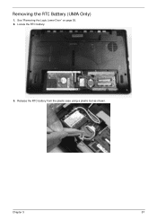
Chapter 3 57 Locate the RTC battery. 3. Release the RTC battery from the plastic case using a plastic tool as shown. Removing the RTC Battery (UMA Only) 1. See "Removing the Logic Lower Door" on page 55. 2.
Chapter 3 57 Locate the RTC battery. 3. Release the RTC battery from the plastic case using a plastic tool as shown. Removing the RTC Battery (UMA Only) 1. See "Removing the Logic Lower Door" on page 55. 2.
Service Guide
Page 68
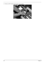
4. Remove the RTC battery from the lower cover as shown. 58 Chapter 3
4. Remove the RTC battery from the lower cover as shown. 58 Chapter 3


