Service Guide
Page 77
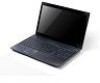
See "External Module Disassembly Process" on page 50. 2. Removing the Upper Cover 1. Remove the eleven (11) screws from the lower cover and four (4) screws from the battery bay. Step Upper Cover (red callout) Size M2.5*8 Battery Bay (green callout) M2*3 Quantity 11 4 Screw Type Chapter 3 67 Turn the computer over.
See "External Module Disassembly Process" on page 50. 2. Removing the Upper Cover 1. Remove the eleven (11) screws from the lower cover and four (4) screws from the battery bay. Step Upper Cover (red callout) Size M2.5*8 Battery Bay (green callout) M2*3 Quantity 11 4 Screw Type Chapter 3 67 Turn the computer over.
Service Guide
Page 100
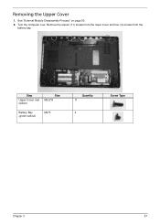
Remove the six (6) screws (in numerical order from the mainboard. Remove the thermal module from 1 to 6) securing the thermal module to the mainboard. 6 3 2 5 1 4 Step Size Quantity Thermal Module SCREW ASSY CPU 4 (CPU) (red THERMAL callouts) Thermal Module M2.5*5 2 (VGA) (green callouts) 5. 4. Screw Type 90 Chapter 3
Remove the six (6) screws (in numerical order from the mainboard. Remove the thermal module from 1 to 6) securing the thermal module to the mainboard. 6 3 2 5 1 4 Step Size Quantity Thermal Module SCREW ASSY CPU 4 (CPU) (red THERMAL callouts) Thermal Module M2.5*5 2 (VGA) (green callouts) 5. 4. Screw Type 90 Chapter 3

Service Guide
Page 122
Replacing the Microphone Cable 1. Place the microphone assembly on the LCD cover. 2. Run the microphone cable along the cable channel outlined in the LCD Module. 3. IMPORTANT: Ensure that the LCD cable runs between the callouts to the LCD cover. 112 Chapter 3 Fold over the foil tabs to secure the microphone cable to avoid trapping when the panel is replaced in red callouts.
Replacing the Microphone Cable 1. Place the microphone assembly on the LCD cover. 2. Run the microphone cable along the cable channel outlined in the LCD Module. 3. IMPORTANT: Ensure that the LCD cable runs between the callouts to the LCD cover. 112 Chapter 3 Fold over the foil tabs to secure the microphone cable to avoid trapping when the panel is replaced in red callouts.
Service Guide
Page 138
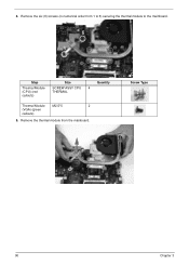
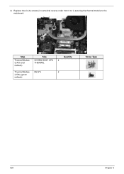
Replace the six (6) screws (in numerical reverse order from 6 to 1) securing the thermal module to the mainboard. 6 3 2 5 1 4 Step Size Quantity Thermal Module SCREW ASSY CPU 4 (CPU) (red THERMAL callouts) Thermal Module M2.5*5 2 (VGA) (green callouts) Screw Type 128 Chapter 3 4.
Replace the six (6) screws (in numerical reverse order from 6 to 1) securing the thermal module to the mainboard. 6 3 2 5 1 4 Step Size Quantity Thermal Module SCREW ASSY CPU 4 (CPU) (red THERMAL callouts) Thermal Module M2.5*5 2 (VGA) (green callouts) Screw Type 128 Chapter 3 4.
Service Guide
Page 155
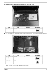
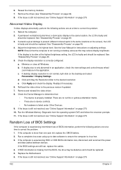
Step Upper Cover Size M2.5*5 Quantity 7 Screw Type 8. Screw Type Chapter 3 145 Replace the seven (7) screws securing the upper cover top the lower cover. Step Upper Cover (red callout) Size M2.5*8 Battery Bay (green callout) M2*3 Quantity 11 4 NOTE: The lower cover may vary depending on the battery bay. Turn the computer over. 7. Replace the ten (11) screws on the lower cover and four (4) screws on your model.
Step Upper Cover Size M2.5*5 Quantity 7 Screw Type 8. Screw Type Chapter 3 145 Replace the seven (7) screws securing the upper cover top the lower cover. Step Upper Cover (red callout) Size M2.5*8 Battery Bay (green callout) M2*3 Quantity 11 4 NOTE: The lower cover may vary depending on the battery bay. Turn the computer over. 7. Replace the ten (11) screws on the lower cover and four (4) screws on your model.
Service Guide
Page 172
... and control/mouse wheel zoom feature in the application. b. Remove and reinstall the video driver. 8. Reseat the memory modules. 7. If the BIOS settings are no red Xs or yellow exclamation marks. • There are still lost, replace the cables. 4. See "Disassembly Process" on page 279. Run the Windows Memory Diagnostic from...
... and control/mouse wheel zoom feature in the application. b. Remove and reinstall the video driver. 8. Reseat the memory modules. 7. If the BIOS settings are no red Xs or yellow exclamation marks. • There are still lost, replace the cables. 4. See "Disassembly Process" on page 279. Run the Windows Memory Diagnostic from...
Service Guide
Page 175
.... Remove and reinstall the audio driver. 5. Click Mixer to 50 and not muted. 6. Ensure that : • The device is properly installed. • There are no red Xs or yellow exclamation marks. • There are no device conflicts. • No hardware is still not resolved, see "Online Support Information" on page 279...
.... Remove and reinstall the audio driver. 5. Click Mixer to 50 and not muted. 6. Ensure that : • The device is properly installed. • There are no red Xs or yellow exclamation marks. • There are no device conflicts. • No hardware is still not resolved, see "Online Support Information" on page 279...
Service Guide
Page 184
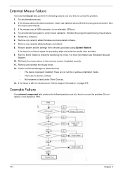
..., perform the following actions one at a time to determine that: • The device is properly installed. Reinstall the program experiencing mouse failure. 5. There are no red Xs or yellow exclamation marks. • There are no device conflicts. • No hardware is still not resolved, see Windows Help and Support. 10.
..., perform the following actions one at a time to determine that: • The device is properly installed. Reinstall the program experiencing mouse failure. 5. There are no red Xs or yellow exclamation marks. • There are no device conflicts. • No hardware is still not resolved, see Windows Help and Support. 10.
Service Guide
Page 217
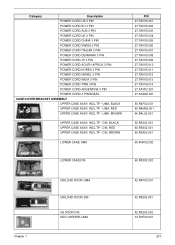
... CORD INDIA 3 PIN POWER CORD TWN 3 PIN POWER CORD ARGENTINA 3 PIN POWER CORD 3 PIN BRAZIL CASE/COVER/BRACKET ASSEMBLY UPPER CASE ASSY, INCL.TP - UMA, RED UPPER CASE ASSY, INCL.TP - DIS, RED UPPER CASE ASSY, INCL.TP - UMA, BLACK UPPER CASE ASSY, INCL.TP - UMA, BROWN UPPER CASE ASSY, INCL.TP -
... CORD INDIA 3 PIN POWER CORD TWN 3 PIN POWER CORD ARGENTINA 3 PIN POWER CORD 3 PIN BRAZIL CASE/COVER/BRACKET ASSEMBLY UPPER CASE ASSY, INCL.TP - UMA, RED UPPER CASE ASSY, INCL.TP - DIS, RED UPPER CASE ASSY, INCL.TP - UMA, BLACK UPPER CASE ASSY, INCL.TP - UMA, BROWN UPPER CASE ASSY, INCL.TP -

Service Guide
Page 224
....6"W WXGA GLARE LP156WH1TLC1 LF 220NIT 16MS 400:1 LK.1560D.013 LK.15606.001 LK.15608.013 ASSY LCD MODULE 15.6"W WXGA GLARE W/ ANTENNA*2, CCD 1.3M, RED 6M.R4M02.002 LCD COVER IMR-RED 60.R4M02.002 214 Chapter 1
....6"W WXGA GLARE LP156WH1TLC1 LF 220NIT 16MS 400:1 LK.1560D.013 LK.15606.001 LK.15608.013 ASSY LCD MODULE 15.6"W WXGA GLARE W/ ANTENNA*2, CCD 1.3M, RED 6M.R4M02.002 LCD COVER IMR-RED 60.R4M02.002 214 Chapter 1
Service Guide
Page 228
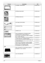
....009 LK.1560E.004 LK.15605.010 LK.1560D.010 LK.15608.011 LK.1560A.004 ASSY LED MODULE 15.6"W WXGA GLARE W/ ANTENNA*2, CCD 1.3M, RED 6M.R4M02.001 LED COVER IMR-RED 60.R4M02.003 218 Chapter 1
....009 LK.1560E.004 LK.15605.010 LK.1560D.010 LK.15608.011 LK.1560A.004 ASSY LED MODULE 15.6"W WXGA GLARE W/ ANTENNA*2, CCD 1.3M, RED 6M.R4M02.001 LED COVER IMR-RED 60.R4M02.003 218 Chapter 1

Service Guide
Page 232
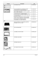
... LP156WH1TLC1 LF 220NIT 16MS 400:1 LK.1560D.013 LK.15606.001 LK.15608.013 ASSY LCD MODULE 15.6"W WXGA GLARE W/ ANTENNA*2, W/O CCD, RED 6M.R4M02.005 LCD COVER IMR-RED LCD BEZEL FOR W/O CMOS 60.R4M02.002 60.R4F02.008 ANTENNA WLAN-MAIN ANTENNA WLAN-AUX 50.R4F02.005 50.R4F02.006...
... LP156WH1TLC1 LF 220NIT 16MS 400:1 LK.1560D.013 LK.15606.001 LK.15608.013 ASSY LCD MODULE 15.6"W WXGA GLARE W/ ANTENNA*2, W/O CCD, RED 6M.R4M02.005 LCD COVER IMR-RED LCD BEZEL FOR W/O CMOS 60.R4M02.002 60.R4F02.008 ANTENNA WLAN-MAIN ANTENNA WLAN-AUX 50.R4F02.005 50.R4F02.006...
Service Guide
Page 236
....1560E.004 LK.15605.010 LK.1560D.010 LK.15608.011 LK.1560A.004 ASSY LED MODULE 15.6"W WXGA GLARE W/ ANTENNA*2, W/O CCD, RED 6M.R4M02.004 LED COVER IMR-RED LCD BEZEL FOR W/O CMOS 60.R4M02.003 60.R4F02.008 ANTENNA WLAN-MAIN ANTENNA WLAN-AUX LED CABLE FOR W/O CMOS 50.R4F02...
....1560E.004 LK.15605.010 LK.1560D.010 LK.15608.011 LK.1560A.004 ASSY LED MODULE 15.6"W WXGA GLARE W/ ANTENNA*2, W/O CCD, RED 6M.R4M02.004 LED COVER IMR-RED LCD BEZEL FOR W/O CMOS 60.R4M02.003 60.R4F02.008 ANTENNA WLAN-MAIN ANTENNA WLAN-AUX LED CABLE FOR W/O CMOS 50.R4F02...


