Quick Start Guide
Page 5
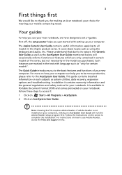
... computing needs. This guide contains detailed information on such subjects as using the keyboard and audio, etc. Follow the instructions on how to complete the installation. For instructions on the screen to use your Acer notebook, we have designed a set of guides: First off, the setup ... Viewing the file requires Adobe Reader. The Quick Guide introduces you to the basic features and functions of the series, but not necessarily in the Aspire product series. In addition it : 1 Click on Start > All Programs > AcerSystem. 2 Click on your notebook. It is not installed on...
... computing needs. This guide contains detailed information on such subjects as using the keyboard and audio, etc. Follow the instructions on how to complete the installation. For instructions on the screen to use your Acer notebook, we have designed a set of guides: First off, the setup ... Viewing the file requires Adobe Reader. The Quick Guide introduces you to the basic features and functions of the series, but not necessarily in the Aspire product series. In addition it : 1 Click on Start > All Programs > AcerSystem. 2 Click on your notebook. It is not installed on...
Quick Start Guide
Page 7
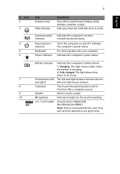
... drive is charging. 2. Touch-sensitive pointing device which functions like the left and right) Touchpad Speaker Microphone 2-in AC mode. Communication indicator Power button / indicator Keyboard Power indicator Indicates the computer's wireless connectivity device status. Turns the computer on and off. For entering data into your computer. Charging: The light shows...
... drive is charging. 2. Touch-sensitive pointing device which functions like the left and right) Touchpad Speaker Microphone 2-in AC mode. Communication indicator Power button / indicator Keyboard Power indicator Indicates the computer's wireless connectivity device status. Turns the computer on and off. For entering data into your computer. Charging: The light shows...
Service Guide
Page 7
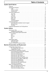
... 1 System Block Diagram 6 UMA 6 Discrete (nVidia 7 Discrete (ATI 8 Your Acer Notebook tour 9 Top View 9 Rear view 10 Left View 11 Right View 12 Base view 13 Indicators 14 Touch Pad Basics 15 Using the Keyboard 16 Lock Keys and embedded numeric keypad 16 Windows Keys 17 Hot Keys... 18 Hardware Specifications and Configurations 19 System Utilities 31 BIOS Setup Utility 31 Navigating the BIOS Utility 31 Aspire 5742/5742G/5742Z/5742ZG BIOS 32 Information 32 ...
... 1 System Block Diagram 6 UMA 6 Discrete (nVidia 7 Discrete (ATI 8 Your Acer Notebook tour 9 Top View 9 Rear view 10 Left View 11 Right View 12 Base view 13 Indicators 14 Touch Pad Basics 15 Using the Keyboard 16 Lock Keys and embedded numeric keypad 16 Windows Keys 17 Hot Keys... 18 Hardware Specifications and Configurations 19 System Utilities 31 BIOS Setup Utility 31 Navigating the BIOS Utility 31 Aspire 5742/5742G/5742Z/5742ZG BIOS 32 Information 32 ...
Service Guide
Page 8
... Replacing the DIMM Modules 151 Replacing the 3G Cover (Discrete Only 152 Replacing the Lower Logic Door 153 Replacing the ODD Module 154 Replacing the Keyboard 156 Replacing the SD Dummy Card 157 Replacing the Battery 158 VIII
... Replacing the DIMM Modules 151 Replacing the 3G Cover (Discrete Only 152 Replacing the Lower Logic Door 153 Replacing the ODD Module 154 Replacing the Keyboard 156 Replacing the SD Dummy Card 157 Replacing the Battery 158 VIII
Service Guide
Page 9
...159 Common Problems 159 Power On Issue 160 No Display Issue 161 Random Loss of BIOS Settings 162 LCD Failure 163 Internal Keyboard Failure 163 Touch Pad Failure 164 Internal Speaker Failure 164 Microphone Record Failure 166 USB Failure (Right side 167 HDD Not Operating...Disk 197 FRU (Field Replaceable Unit) List 199 Aspire Exploded Diagrams 200 Main Assembly 200 Lower Cover 202 LCD Assembly 203 LED Assembly 204 Aspire FRU List 205 Screw List 229 Model Definition and Configuration 231 Aspire 5742/5742G 231 Aspire 5742Z/5742ZG 257 Test Compatible Components 273 Online ...
...159 Common Problems 159 Power On Issue 160 No Display Issue 161 Random Loss of BIOS Settings 162 LCD Failure 163 Internal Keyboard Failure 163 Touch Pad Failure 164 Internal Speaker Failure 164 Microphone Record Failure 166 USB Failure (Right side 167 HDD Not Operating...Disk 197 FRU (Field Replaceable Unit) List 199 Aspire Exploded Diagrams 200 Main Assembly 200 Lower Cover 202 LCD Assembly 203 LED Assembly 204 Aspire FRU List 205 Screw List 229 Model Definition and Configuration 231 Aspire 5742/5742G 231 Aspire 5742Z/5742ZG 257 Test Compatible Components 273 Online ...
Service Guide
Page 14
...; 381 (W) x 253 (D) x 25/34 (H) mm (15 x 9.96 x 0.98/1.33 inches) Weight: • 2.6 kg (5.74 lbs.) with 6-cell battery pack Input and control Keyboard: • 103-/104-/107-key Acer FineTip keyboard with independent standard numeric keypad, international language support Touchpad: • Multi-gesture touchpad, supporting two-finger scroll, pinch, rotate, flip Media keys...
...; 381 (W) x 253 (D) x 25/34 (H) mm (15 x 9.96 x 0.98/1.33 inches) Weight: • 2.6 kg (5.74 lbs.) with 6-cell battery pack Input and control Keyboard: • 103-/104-/107-key Acer FineTip keyboard with independent standard numeric keypad, international language support Touchpad: • Multi-gesture touchpad, supporting two-finger scroll, pinch, rotate, flip Media keys...
Service Guide
Page 19
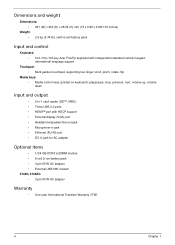
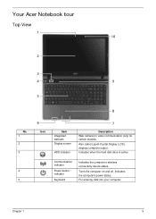
Also called Liquid-Crystal Display (LCD), displays computer output. For entering data into your computer. Indicates when the hard disk drive is active. Communication indicator Power button / indicator Keyboard Indicates the computer's wireless connectivity device status. Chapter 1 9 Your Acer Notebook tour Top View 1 10 2 3 4 9 5 No. 1 2 3 4 5 8 6 Icon Item Integrated webcam Display screen HDD indicator 7 Description Web camera for video communication (only for certain models). Turns the computer on and off. Indicates the computer's power status.
Also called Liquid-Crystal Display (LCD), displays computer output. For entering data into your computer. Indicates when the hard disk drive is active. Communication indicator Power button / indicator Keyboard Indicates the computer's wireless connectivity device status. Chapter 1 9 Your Acer Notebook tour Top View 1 10 2 3 4 9 5 No. 1 2 3 4 5 8 6 Icon Item Integrated webcam Display screen HDD indicator 7 Description Web camera for video communication (only for certain models). Turns the computer on and off. Indicates the computer's power status.
Service Guide
Page 26
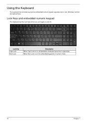
Using the Keyboard The keyboard has full-sized keys and an embedded numeric keypad, separate cursor, lock, Windows, function and special keys. Lock Keys and embedded numeric keypad The keyboard has two lock keys which you can toggle on , the embedded keypad is in uppercase. Lock key Caps Lock Num Lock Description When Caps Lock is on and off. When Num Lock is on, all alphabetic characters typed are in numeric mode. 16 Chapter 1
Using the Keyboard The keyboard has full-sized keys and an embedded numeric keypad, separate cursor, lock, Windows, function and special keys. Lock Keys and embedded numeric keypad The keyboard has two lock keys which you can toggle on , the embedded keypad is in uppercase. Lock key Caps Lock Num Lock Description When Caps Lock is on and off. When Num Lock is on, all alphabetic characters typed are in numeric mode. 16 Chapter 1
Service Guide
Page 27
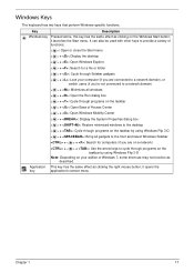
... through programs on the taskbar < > + : Open Ease of Windows 7, some shortcuts may not function as clicking the right mouse button; Chapter 1 17 Windows Keys The keyboard has two keys that perform Windows-specific functions. it opens the key application's context menu.
... through programs on the taskbar < > + : Open Ease of Windows 7, some shortcuts may not function as clicking the right mouse button; Chapter 1 17 Windows Keys The keyboard has two keys that perform Windows-specific functions. it opens the key application's context menu.
Service Guide
Page 32
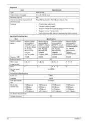
... simultaneously Features Specification AC7T-A10B 103-US/104-UK keys Yes Plug USB keyboard to the USB port directly: Yes • Phantom key auto detect • Overlay numeric keypad • Support independent pgdn/pgup/pgup/home/end keys • ...
... simultaneously Features Specification AC7T-A10B 103-US/104-UK keys Yes Plug USB keyboard to the USB port directly: Yes • Phantom key auto detect • Overlay numeric keypad • Support independent pgdn/pgup/pgup/home/end keys • ...
Service Guide
Page 59
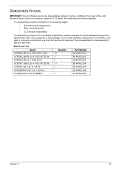
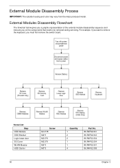
The disassembly process is faulty, such as the camera, antenna or LCD panel, the whole module must first remove the keyboard, then disassemble the inside assembly frame in the succeeding disassembly sections illustrate the entire disassembly sequence. Main Screw List Screw Quantity Part Number SCREW 2.5D ...
The disassembly process is faulty, such as the camera, antenna or LCD panel, the whole module must first remove the keyboard, then disassemble the inside assembly frame in the succeeding disassembly sections illustrate the entire disassembly sequence. Main Screw List Screw Quantity Part Number SCREW 2.5D ...
Service Guide
Page 60
... a graphic representation of the external module disassembly sequence and instructs you must first remove the switch board. For example, if you want to remove the keyboard, you on the components that need to be removed during servicing. Screw List Step ODD Module ODD Bracket Logic lower door 3G Cover WLAN Module...
... a graphic representation of the external module disassembly sequence and instructs you must first remove the switch board. For example, if you want to remove the keyboard, you on the components that need to be removed during servicing. Screw List Step ODD Module ODD Bracket Logic lower door 3G Cover WLAN Module...

Service Guide
Page 74
Using a flat plastic tool, release the six (6) keyboard locks to expose the keyboard FPC. 64 Chapter 3 Pry up the center of the keyboard and lift it up and over to remove the keyboard from the upper cover. 3. Removing the Keyboard 1. See "Removing the Logic Lower Door" on page 55. 2.
Using a flat plastic tool, release the six (6) keyboard locks to expose the keyboard FPC. 64 Chapter 3 Pry up the center of the keyboard and lift it up and over to remove the keyboard from the upper cover. 3. Removing the Keyboard 1. See "Removing the Logic Lower Door" on page 55. 2.

Service Guide
Page 75
Chapter 3 65 Release the locking latch and disconnect the FPC from the mainboard connector. 5. 4. Lift the keyboard clear of the upper cover.
Chapter 3 65 Release the locking latch and disconnect the FPC from the mainboard connector. 5. 4. Lift the keyboard clear of the upper cover.

Service Guide
Page 166
Connect the keyboard FFC to the mainboard and close the locking latch to lock. 156 Chapter 3 Place the keyboard face down firmly to secure the cable in place. 3. Press down on the palm rest. 2. Replacing the Keyboard 1. Replace the keyboard by first lining up the bottom edge.
Connect the keyboard FFC to the mainboard and close the locking latch to lock. 156 Chapter 3 Place the keyboard face down firmly to secure the cable in place. 3. Press down on the palm rest. 2. Replacing the Keyboard 1. Replace the keyboard by first lining up the bottom edge.
Service Guide
Page 169
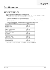
...Obtain the failing symptoms in as much detail as a guide for computer problems. NOTE: The diagnostic tests are intended to test only Acer products. Non-Acer products, prototype cards, or modified options can give false errors and invalid system responses. 1. Symptoms (Verified) Go To Power On... Issue Page 160 No Display Issue Page 161 LCD Failure Page 163 Internal Keyboard Failure Page 163 TouchPad Failure Page 164 Internal ...
...Obtain the failing symptoms in as much detail as a guide for computer problems. NOTE: The diagnostic tests are intended to test only Acer products. Non-Acer products, prototype cards, or modified options can give false errors and invalid system responses. 1. Symptoms (Verified) Go To Power On... Issue Page 160 No Display Issue Page 161 LCD Failure Page 163 Internal Keyboard Failure Page 163 TouchPad Failure Page 164 Internal ...
Service Guide
Page 173
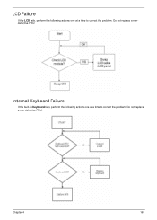
Do not replace a non-defective FRU: Chapter 4 163 Do not replace a nondefective FRU: Internal Keyboard Failure If the built-in Keyboard fails, perform the following actions one at a time to correct the problem. LCD Failure If the LCD fails, perform the following actions one at a time to correct the problem.
Do not replace a non-defective FRU: Chapter 4 163 Do not replace a nondefective FRU: Internal Keyboard Failure If the built-in Keyboard fails, perform the following actions one at a time to correct the problem. LCD Failure If the LCD fails, perform the following actions one at a time to correct the problem.

Service Guide
Page 189
... Build AMT Table PPM Initialization HECIDRV Initialization Description Enter BDS entry Install Hotkey service ASF Initialization PCI enumeration PCI resource assign complete PCI enumeration complete Keyboard Controller, Keyboard and Mouse initialization Video device initialization Error report device initialization USB host controller initialization USB BUS driver initialization USB device driver initialization Console device...
... Build AMT Table PPM Initialization HECIDRV Initialization Description Enter BDS entry Install Hotkey service ASF Initialization PCI enumeration PCI resource assign complete PCI enumeration complete Keyboard Controller, Keyboard and Mouse initialization Video device initialization Error report device initialization USB host controller initialization USB BUS driver initialization USB device driver initialization Console device...

Service Guide
Page 193
Jumper and Connector Locations Top View UMA Chapter 5 Item JLED1 JLVDS1 JSPK1 JMIC2 JKB1 JODD1 Description Connect to Powerboard (FFC) Connect to LED / CCFL Connector Connect to Left Speaker Connect to internal MIC Connect to Keyboard Connect to ODD board (FFC) Item JTP1 JUSB2 SW1/SW2 LED1/LED2 LED3/LED4 JCR1 Description Connect to Touch pad (FFC) Connect to USB Board (FFC) Left button / Right button Power State Indicator Battery Charging Indicator Connect to SD/MMC card Chapter 1 183
Jumper and Connector Locations Top View UMA Chapter 5 Item JLED1 JLVDS1 JSPK1 JMIC2 JKB1 JODD1 Description Connect to Powerboard (FFC) Connect to LED / CCFL Connector Connect to Left Speaker Connect to internal MIC Connect to Keyboard Connect to ODD board (FFC) Item JTP1 JUSB2 SW1/SW2 LED1/LED2 LED3/LED4 JCR1 Description Connect to Touch pad (FFC) Connect to USB Board (FFC) Left button / Right button Power State Indicator Battery Charging Indicator Connect to SD/MMC card Chapter 1 183
Service Guide
Page 194
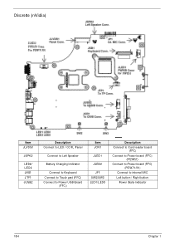
Discrete (nVidia) Item JLVDS1 JSPK2 LED2/ LED4 JKB1 JTP1 JUSB2 Description Connect to LED / CCFL Panel Connect to Left Speaker Battery Charging Indicator Connect to Keyboard Connect to Touch pad (FFC) Connect to Power USB Board (FFC) Item JCR1 JLED1 JLED2 JP1 SW2/SW3 LED1/LED3 Description Connect to Card reader board (FFC) Connect to Power board (FFC) (PEW51) Connect to Power board (FFC) (PEW71/91) Connect to internal MIC Left button / Right button Power State Indicator 184 Chapter 1
Discrete (nVidia) Item JLVDS1 JSPK2 LED2/ LED4 JKB1 JTP1 JUSB2 Description Connect to LED / CCFL Panel Connect to Left Speaker Battery Charging Indicator Connect to Keyboard Connect to Touch pad (FFC) Connect to Power USB Board (FFC) Item JCR1 JLED1 JLED2 JP1 SW2/SW3 LED1/LED3 Description Connect to Card reader board (FFC) Connect to Power board (FFC) (PEW51) Connect to Power board (FFC) (PEW71/91) Connect to internal MIC Left button / Right button Power State Indicator 184 Chapter 1


